tracing is one of the earliest forms of computer arts, a good read if you’ve never heard of it via retweeted by BitcraftLab. the more recent takes, with bigger formats and the use of colors always strike me with the complexity of their patterns and yet plotters use the simplest tools available: points, lines and curves. there are so many things to say about this topic but that’s way beyond the scope of this humble article. what I like the most is that, as opposed to a printer which will output a clean snapshot of a sketch, a plotter will make (lots of) mistakes.
last december I saw Anders Hoff having bags of fun with his plotter and two weeks ago the XY plotter 2.0 arrived. I’m probably the clumsiest handyman on the face of the earth, yet after 10 hours (over 3 days), I managed to mount it. later, I found this carefully documented step by step tutorial, it would have helped.
some things I did to make my life easier
- lower the servo by a good centimeter to use regular pens or brushes ; by default they are quickly blocked by the beam
- use one of the 30*4 screws & a bolt at the end of the lever and tie the elastic on this rather than the default setting ; the pen needs to be pressed on the paper and by default, the elastic’s tension is to weak
- replace the 30*4 screws by 60*4 screws as it allows bigger pens to fit
- use a 50*50*3cm wooden frame and a linoleum surface. I attached the plotter to the frame to provides better stability as the plotter may move a bit during fast or frequent moves. linoleum is flat, waterproof, easy to clean up and good to stick or move crepe tape (something you should use if you don’t want to tear off the paper when you remove it) but more importantly the linoleum damps the “pen down” move, when plotting big sketches this noise becomes extremely bothering.
on a side note, the cables from the board to the pen are short, they can’t reach the top left corner (x=0, y=1) I should change them to use the whole surface.
then I tried to trace something and it worked! it was properly calibrated and just worked.
unfortunately, the available software are rather limited ; mDraw is a generic purpose tool: you have to place the sketch manually, on import, it resizes every sketch to a 15*15 cm representation, it’s possible to set the width and height yet no way to set the X/Y coordinates which is really irritating (if you want 2 or more colors, it’s a no go). well at least it properly uploads the firmware to the arduino board and gets you started quickly.
there is a second software called BenBox, more of “technical” thing, I couldn’t get it to work (Win 10) even though I tried to install & run each and every version I could get my hands on.
the third option is to use Processing but then again the demo won’t work for some reason (controls won’t show once connected) and the code on the repo is pretty cryptic for a beginner like me. I gave up after 4 hours of struggle but I should really try harder and make some sense of all this, especially the GCode bit that seems to be well supported. some leads: lead 1 , lead 2, lead 3, lead 4
the last option is to use Python and send the CNC formatted instructions directly to the board, let’s call it the advanced approach (probably the most efficient).
after the first tests, I tried to print something more complex and used the result of the MST from the previous article.
the sketch is made of 23714 edges, it’s a very tricky subject as there are numerous small elements.
little did I know how much time it would take (hint: loooooooong ), which, after years spent working in (near) real-time graphics, was a bit unsettling.
after 15 hours of work, the plotter had not even reached 10% of the total task. this is because strokes can be traced in a random order ; it doesn’t matter if we start at the top, the bottom, or the center. each time the plotter moves the pen to trace the next segment, it’ll take some time (roughly 50px/second with the default settings), then it’ll take some time again to draw the line. the servo moves pretty fast so the pen up/down move’s duration is negligible.
to help visualize what happens, I painted the unordered segments with a hsl mode where the hue corresponds to their position in the array to the left and a single semi transparent polyline that goes through all the edges’ centers (click for larger pics).
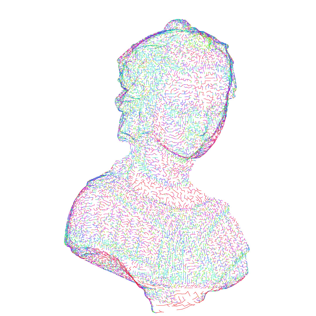
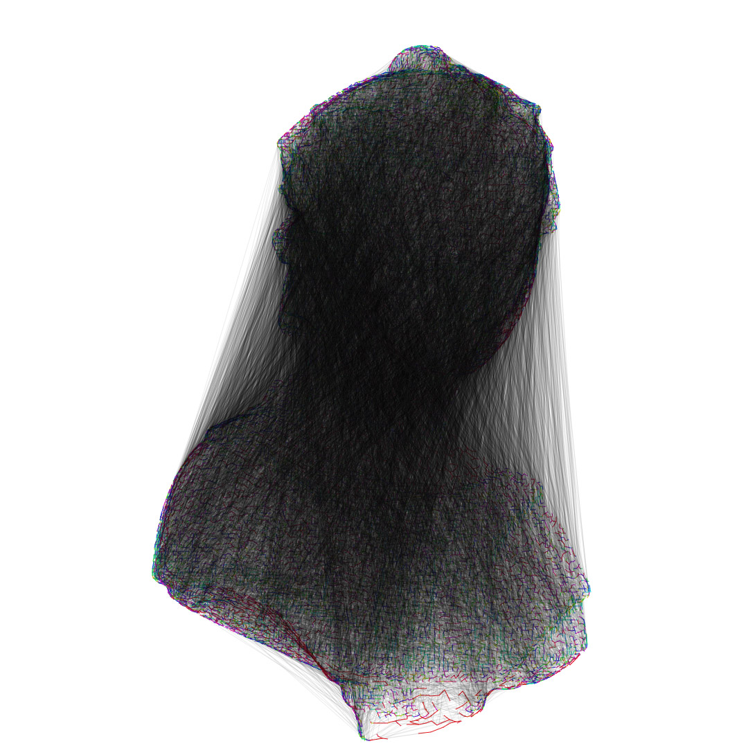
we can clearly see that the edges are almost randomly distributed, so the plotter will have to do the series of moveTo (to the right) + all the moveTos/lineTos described by the segments (to the left) to finish the work. the length of the grey polyline is ~9.569.766 pixels. if we don’t resize the sketch and if the plotter moves at a speed of 50px/s it means it would take 43h for the plotter to simply move over the drawing.
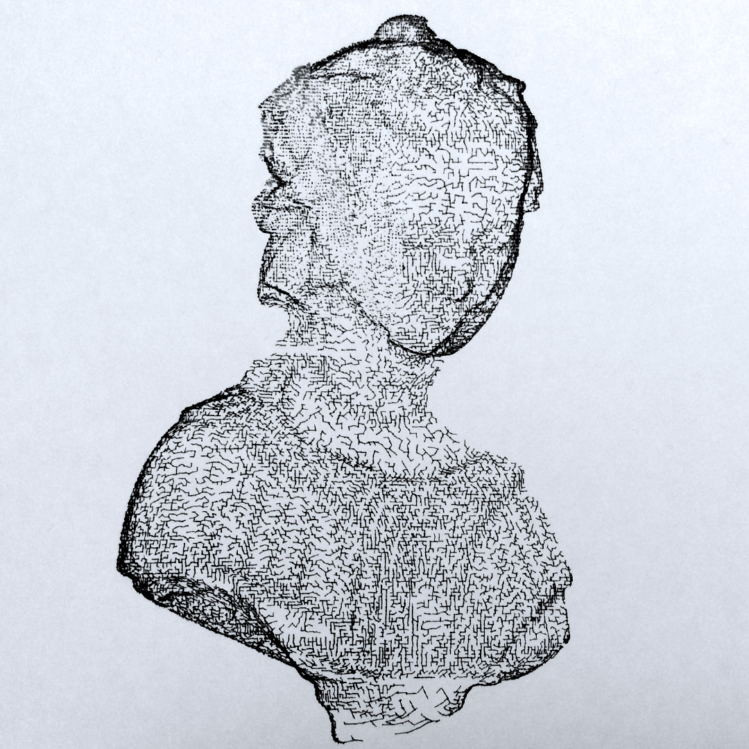
if we want to plot something even fairly simple in a reasonable amount of time, we need to find a way to sort the line segments. below is the same graph with vertices sorted on the horizontal axis.


the length of the path between all segments’ centers is now ~6.674.923 px which is 66%of the original, so far so good ( + the “victorian veiled widow” comes for free)
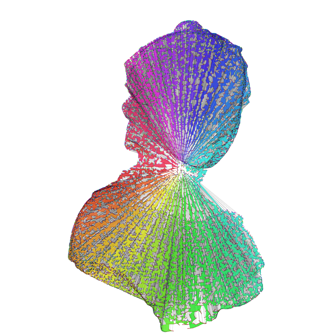
let’s try with a polar sort (sorting by angle to the center):


a ~2.208.824 px long polyline, 20% of the original work time!
in fact this boils down to finding the shortest path between edges ; this is a very famous problem in graph theory that usually goes by the name of Traveling Salesman Problem or TSP. there are various ways to address it, often involving neural networks or genetic algorithm (I believe the latter is more robust) but there’s another approach called Simulated Annealing that mimics the way atomic structure reorganizes itself in a medium as its temperature lowers. I had a take at the algorithm in actionscript a while back, and tried to apply this to find the shortest path. if it is very slow to obtain decent shortest path, it is relatively fast to obtain a coarse shortest path, here’s a codepen (click to reset).
so I split the polar sorted segment set into bins of 500 vertices and applied the TSP on each bin, it looked like this:
 the total length of all the bins using a coarse TSP was ~79.446 px, roughly 3.6% of the polar sorted version and ~0.7% of the original ; theoretically ~30 minutes to move the pen around. this doesn’t take the actual drawing into account but it’s already much better.
when this sorting problem was taken care of, I sent the file for plot and got this brilliant failure (all apologies for the crappy pictures):
you can clearly see the clockwise progression of the plot and the point at which it decided to stipple rather than draw lines. this is because I thought it would be clever to use a contraption of my own, namely 2 springs pushing the caret against the lever to pinch the pen ; my plan was to allow a simpler pen swap. this – of course – induced mechanical float so after hitting the board 2500 times, the pen went (╯°□°)╯︵ ┻━┻
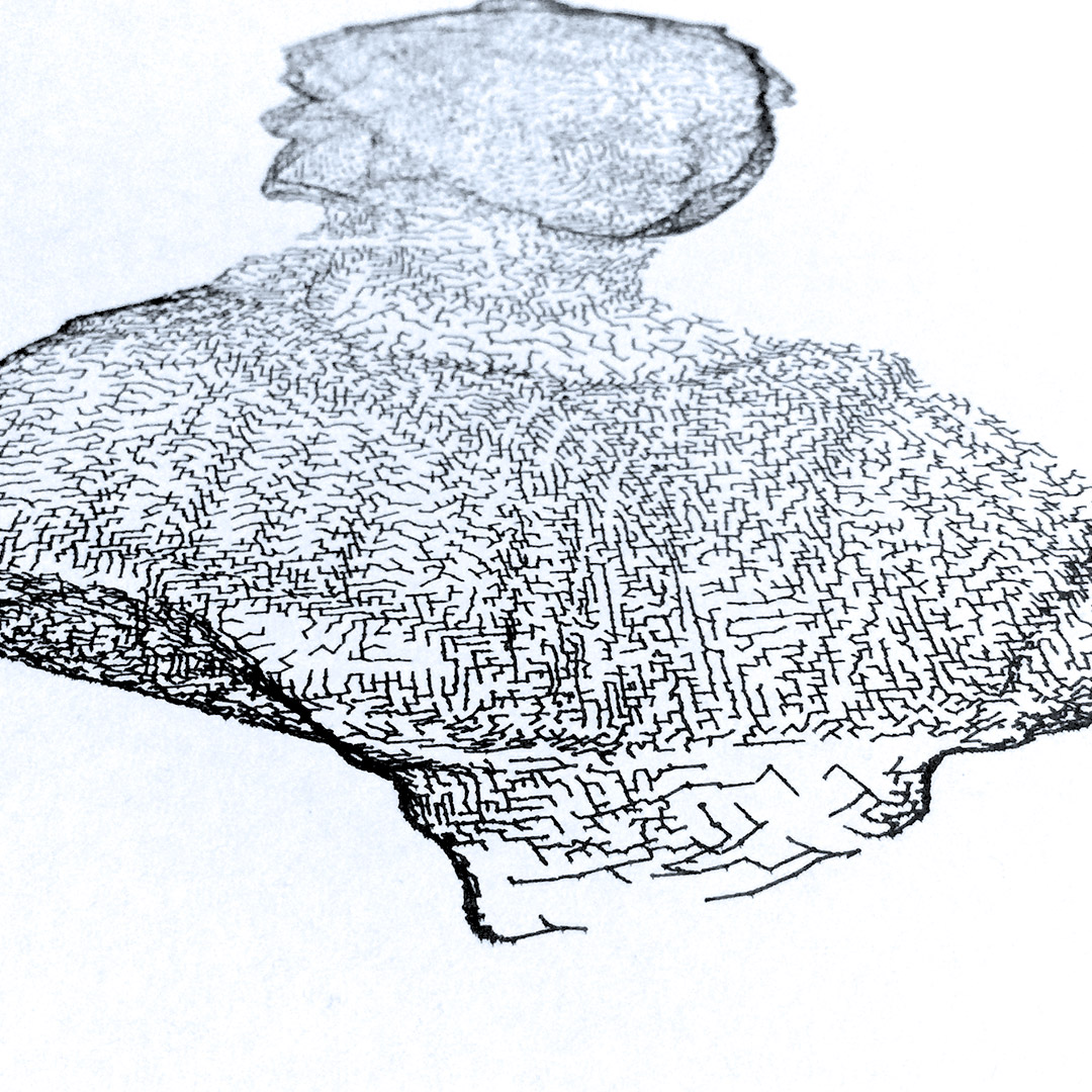
most strokes in this sketch have a length equal to or shorter than 1 mm, if there is mechanical float, it won’t work ; the pen will go down, the plotter will move it in a given direction but not enough to compensate the float so the pen will remain stuck. during the plot, I locked the pen firmly and added an extra elastic to maintain it on the surface of the paper. from “noon” to nine, the drawing worked nicely and only took ~5h30, as compared to the first attempt it was a brilliant failure.
I believe the way the svg is formatted is important too ; in some previous attempts, I described each stroke as a <path> element resulting in a 2.5+ Mo files. here I turned coordinates into ints and packed each TSP bin as a path element, the file became 450 Ko and the plotter seemed happier about it.
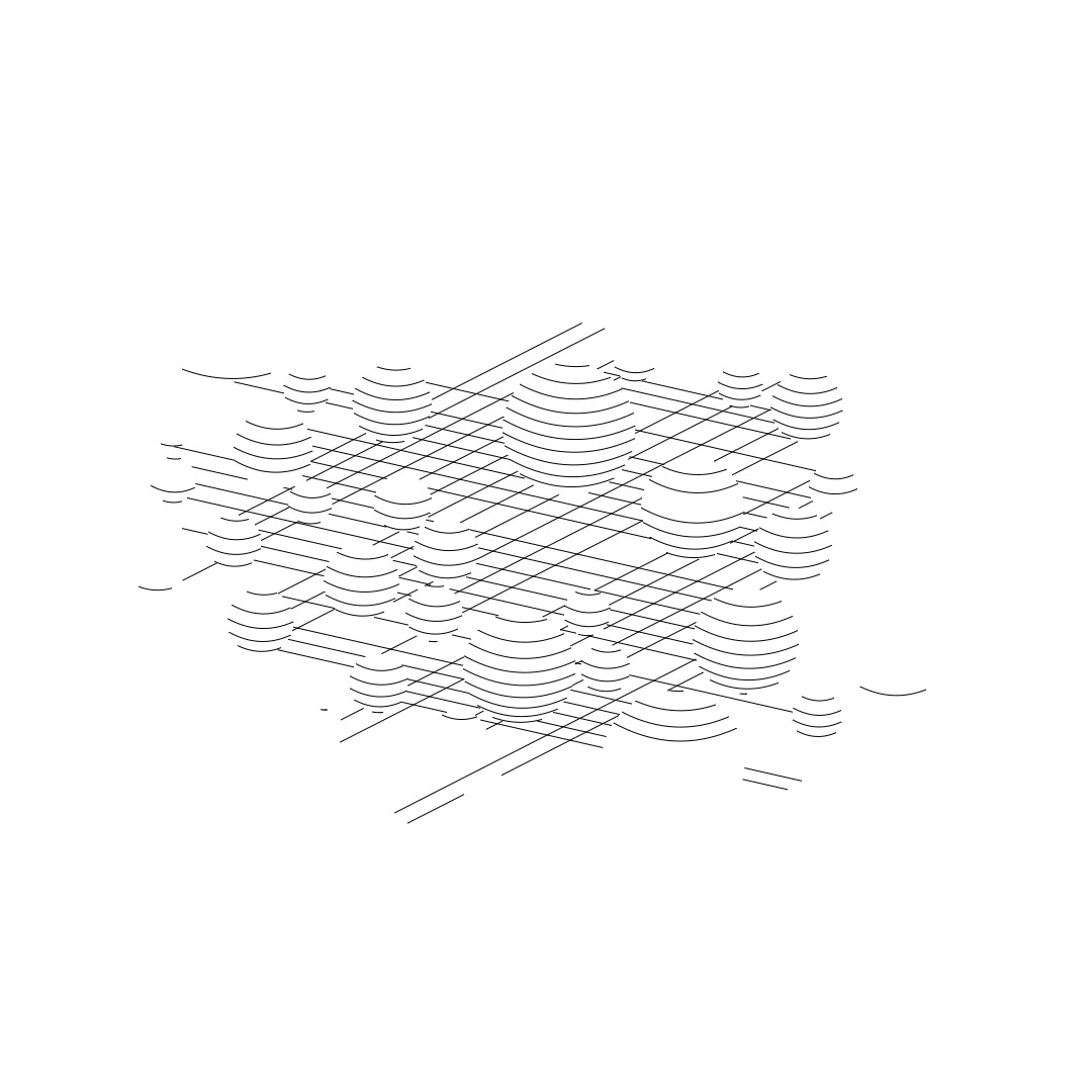
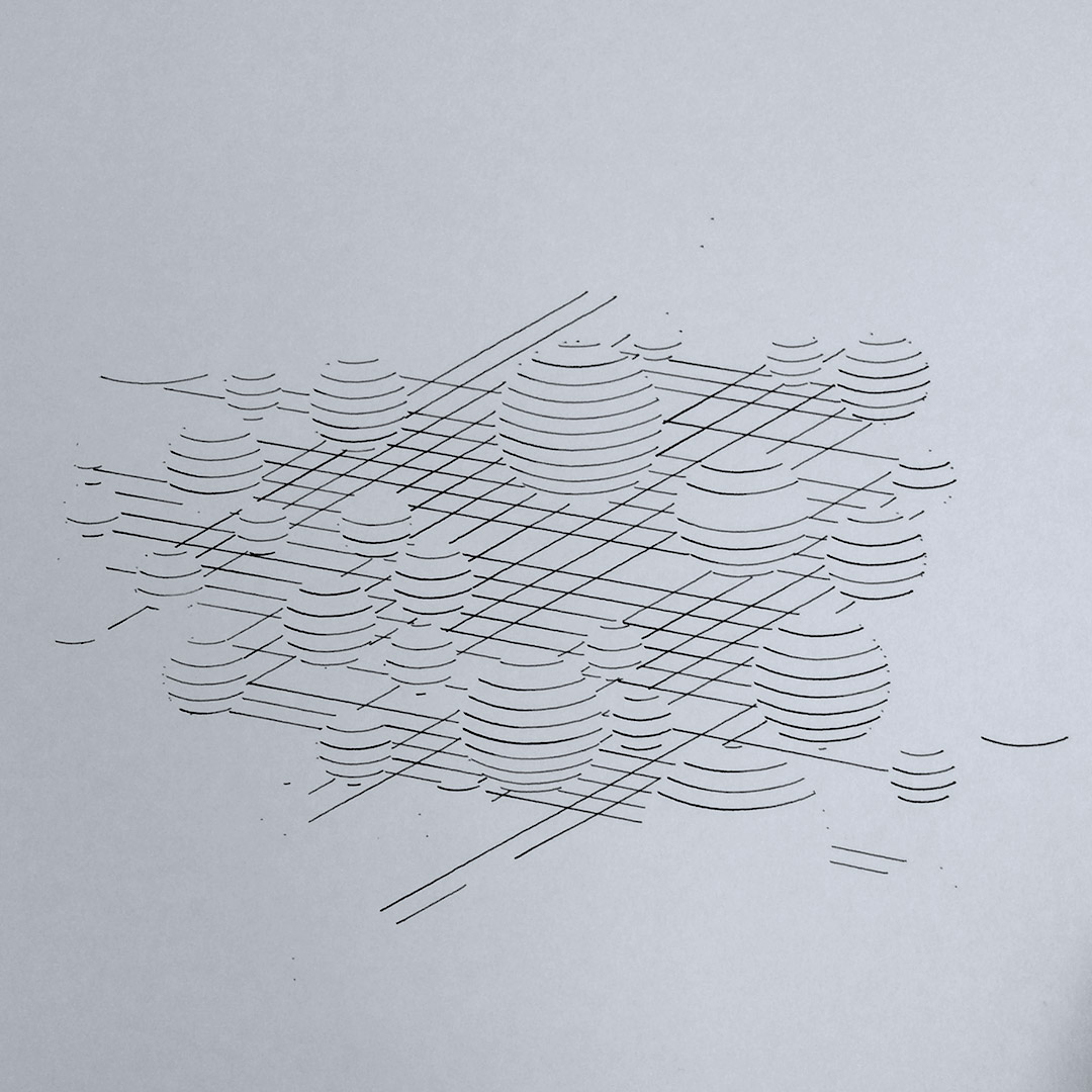
there are still things that I don’t understand ; for instance this “hulled clusters” version of the mesh took roughly 20 minutes to plot for a 25 cm high drawing (which is big for the max surface is 31*38 cm).

and this “unknown pleasure”-ish version made of 99 series of segments took almost an hour (it’s 32cm high).

to improve the render time, we can group series of consecutive segments into a path, minimize the moveTos, simplify the paths, use SVG’s built-in shapes ; for instance this series of shapes uses straight lines and quadratic curves (this is 2D btw).
the Curve SVG instruction is much faster than tracing the same with a series of segments but at the end of the day, a complex shape will take more time than a simple shape…
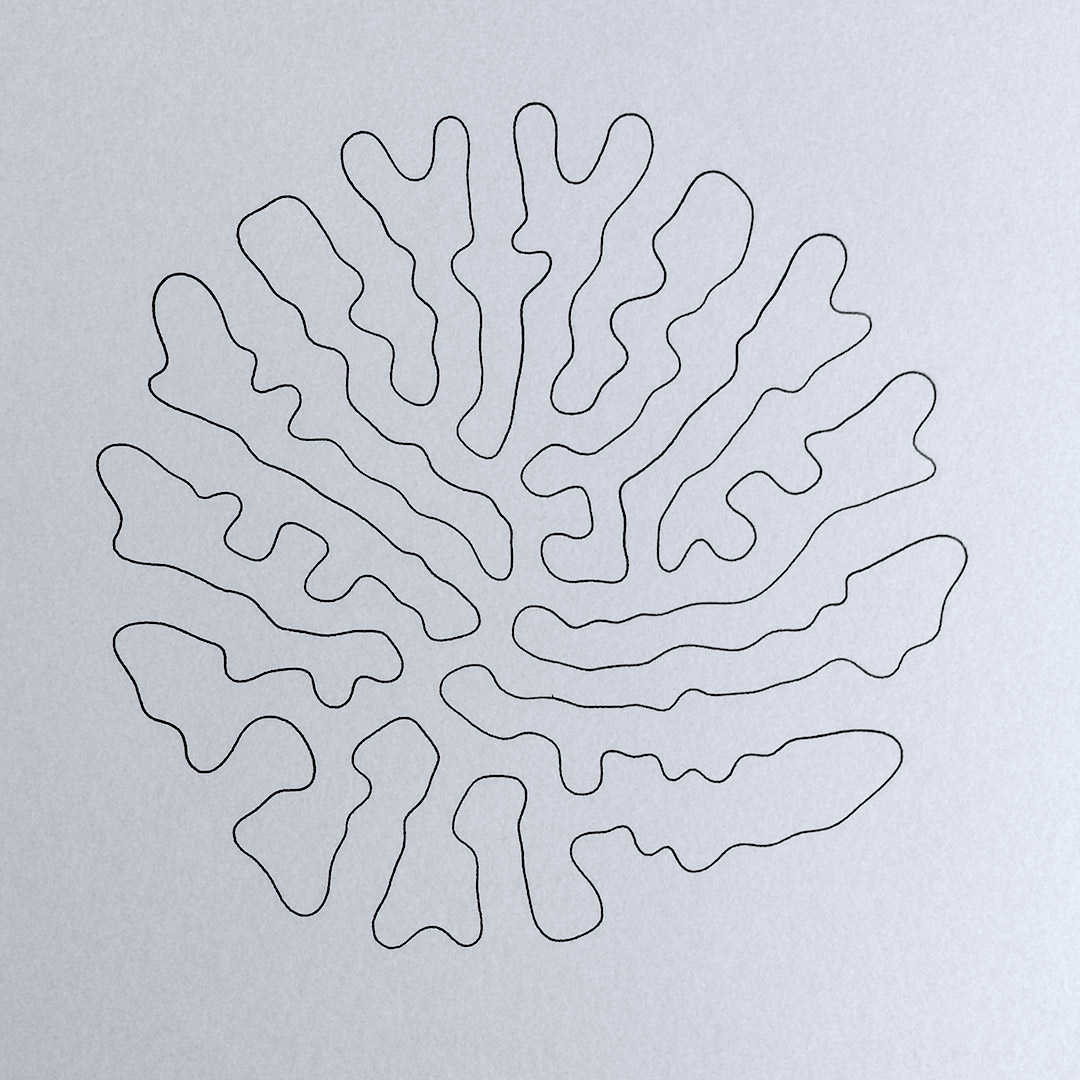
now as I mentioned Andreas at the beginning of the article, I had to try this shape! (I don’t know how it’s called for realz, I called it Growth, it’s a recursively subdividing polyline)
and TADA! (15*15cm)
what about pointillism?
dots have a lot in common with particles, you need lots of them to get something visually interesting. fortunately, computers like to compute and plotters like to plot so with a proper sorting method, sky is the limit (well not exactly but you get the idea). there are techniques I’d like to explore, the first is the stippling, the second is the dithering, both can lead to better dots distributions and allow optical grayscale (shades of grey by means of dots densities). dithering can lead to photorealistic representations and can be performed on the GPU. I’ll write about it if/when I manage to get it to work. for now, I’ll leave you with this zebra-striped giraffe 
and its glorious plotted counterpart (26*13 cm, ~4h, 20.878 points)
one sure thing is that I’ve never been so excitedly happy with any device for the past 10 years :)
also I’ve posted some intermediate renders/bugs here
Waw ! It’s a very cool device to play with !
I made some tests with a 3D-printer but it was really too long and I gave up.
I’m jealous of your patience :)
– by the way, the “Growth demo” is awesome ; thank you for sharing it –
I’m studying the code of the “Growth demo” …
I’m – really -sorry but I have one critic about it :
The way you define your class and assign the functions to the prototype doesn’t make any sense because you already defined the function at the level of your class…
The goal of a prototype is to NOT defined every function for every instance.
In your code, when you create an instance of an object, you create first every function – for each instance – and then you assign these function to the prototype… It’s not how the code should work.
You should have a very small class constructor that contains the properties of your class only (or the getter/setter because in that particular case, you have to put it in the constructor) , and every function should be defined directly on the prototype of your class.
For example :
var Obj = function(name){
this.name = name;
this.property = “youpî”;
this.number = 12;
this.init();
console.log(this.number);
this.__defineGetter(“prop”,function(){return “bam”});
}
Obj.prototype.init = function(){
this.number *= 2;
}
Obj.prototype.test = function(){
alert(“PAF !”);
}
And if you want to extend your class, you can do it like that
var SecondObj = function(name,numberMulti){
Obj.call(this,name);
this.number *= numberMulti;
}
//override init :
SecondObj.prototype.init = function(){
//the “super” works like that :
Obj.prototype.init.call(this);
this.number += 1000;
}
SecondObj .prototype = Object.create(Obj.prototype);
SecondObj .prototype.constructor = SecondObj;
I hope you will not feel agressed by my post because your code in itself is great and I love it :)
Sorry I made a mistake concerning the “extends”
SecondObj .prototype = Object.create(Obj.prototype);
SecondObj .prototype.constructor = SecondObj;
should be written directly after the constructor definition and BEFORE you assign some functions to the prototype , because if you apply it at the end of the code like I did, the whole prototype of the object will be replaced by the prototype of the class Obj and all the function previously defined on the prototype of SecondObj will be lost.
The correct full code is :
var SecondObj = function(name,numberMulti){
Obj.call(this,name);
this.number *= numberMulti;
}
SecondObj .prototype = Object.create(Obj.prototype);
SecondObj .prototype.constructor = SecondObj;
//override init :
SecondObj.prototype.init = function(){
//the “super” works like that :
Obj.prototype.init.call(this);
this.number += 1000;
}
hey !
I can’t even think of how much time a 3D print would take, it would drive me mad :)
thanks for your kind words about the demo, glad you like it :)
as far as the code is concerned, I have to disagree but that’s a long story, I’ll write a mail instead. for now you can refer to Edan Kwan’s blog post: http://blog.edankwan.com/post/javascript-class
Hello !
I read the Edan Kwan’s blog post but as he sais himself : “I am gonna share my standard”
This is ITS standard not how things really works :)
As I said before, the goal of a prototype is to assign a function to an Object without define it for every instance.
Because when you have a class like that :
var MyClass = function(){
function myFunction(){
}
}
The function “myFunction” is redefined each time you create an instance of MyClass. It’s like you create a full-class for each instanciation because what you’re doing (when you instanciate MyClass) is creating a new empty object and then assign it some function inside.
When you assign a function to the prototype of an object, you create it once for all because the functions are “linked” to the object.
Let me imagine an example you will understand…
If you create a particle engine using a texture to render the particle, I think you will use a single instance of the texture that you share to every particle, right ?
Well, the prototype is your texture and the objects are your particles. Every object share the same prototype then it’s doesn’t make any sense to redefine the function of the prototype again and again.
You are not forced to believe me on speach :)
I made a comparison test, you can find the code here
http://pastebin.com/1vMDsrUW
Your approach is almost 2 times slower than mine ! (on my computer)
Happy new year by the way :D
your test is not correct :) in my case, the function must be called and return the constructor defined within the function. try this: http://pastebin.com/PFEuCcZg
it’s slightly faster for obj2 but it’s more about readability than perfs
Look like you’re right…
Thank you for your time & code and sorry about the critic :)