update 210525:
Mario Carrillo was kind enough to port the code samples to ES6, something I’ve been willing to do for years.
so check out his repo: https://github.com/marioecg/gpu-party/ ( and check out his work while you’re at it )
particles are awesome.
I can’t tell how many particle engines I’ve written for the past 15 years but I’d say a lot. one reason is that it’s easy to implement and quickly gives good looking / complex results.
in august 2014, I started a year-long project that never shipped (which I playfully codenamed “the silent failure”), the first thing they asked for was a particle engine to emulate a shitload of particles.
the way to go in this case is to use a GPGPU approach a.k.a. FBO particles. it is a fairly well documented technique, there were working examples of FBO particles running in THREE.js and especially this one by Joshua Koo & Ricardo Cabello
in a nutshell, 2 passes are required:
- simulation: uses a Data Texture as an input, updates the particles’ positions and writes them back to a RenderTarget
- render: uses the RenderTarget to distribute the particles in space and renders the particles to screen
the first pass requires a bi-unit square, an orthographic camera and the ability to render to a texture. the second pass is your regular particles rendering routine with a twist on how to retrieve the particle’s position.
the FBO class goes like:
|
1 2 3 4 5 6 7 8 9 10 11 12 13 14 15 16 17 18 19 20 21 22 23 24 25 26 27 28 29 30 31 32 33 34 35 36 37 38 39 40 41 42 43 44 45 46 47 48 49 50 51 52 53 54 55 56 57 58 59 60 61 62 63 64 65 66 67 68 69 70 71 72 73 74 |
var FBO = function( exports ){ var scene, orthoCamera, rtt; exports.init = function( width, height, renderer, simulationMaterial, renderMaterial ){ gl = renderer.getContext(); //1 we need FLOAT Textures to store positions //https://github.com/KhronosGroup/WebGL/blob/master/sdk/tests/conformance/extensions/oes-texture-float.html if (!gl.getExtension("OES_texture_float")){ throw new Error( "float textures not supported" ); } //2 we need to access textures from within the vertex shader //https://github.com/KhronosGroup/WebGL/blob/90ceaac0c4546b1aad634a6a5c4d2dfae9f4d124/conformance-suites/1.0.0/extra/webgl-info.html if( gl.getParameter(gl.MAX_VERTEX_TEXTURE_IMAGE_UNITS) == 0 ) { throw new Error( "vertex shader cannot read textures" ); } //3 rtt setup scene = new THREE.Scene(); orthoCamera = new THREE.OrthographicCamera(-1,1,1,-1,1/Math.pow( 2, 53 ),1); //4 create a target texture var options = { minFilter: THREE.NearestFilter,//important as we want to sample square pixels magFilter: THREE.NearestFilter,// format: THREE.RGBFormat,//could be RGBAFormat type:THREE.FloatType//important as we need precise coordinates (not ints) }; rtt = new THREE.WebGLRenderTarget( width,height, options); //5 the simulation: //create a bi-unit quadrilateral and uses the simulation material to update the Float Texture var geom = new THREE.BufferGeometry(); geom.addAttribute( 'position', new THREE.BufferAttribute( new Float32Array([ -1,-1,0, 1,-1,0, 1,1,0, -1,-1, 0, 1, 1, 0, -1,1,0 ]), 3 ) ); geom.addAttribute( 'uv', new THREE.BufferAttribute( new Float32Array([ 0,1, 1,1, 1,0, 0,1, 1,0, 0,0 ]), 2 ) ); scene.add( new THREE.Mesh( geom, simulationMaterial ) ); //6 the particles: //create a vertex buffer of size width * height with normalized coordinates var l = (width * height ); var vertices = new Float32Array( l * 3 ); for ( var i = 0; i < l; i++ ) { var i3 = i * 3; vertices[ i3 ] = ( i % width ) / width ; vertices[ i3 + 1 ] = ( i / width ) / height; } //create the particles geometry var geometry = new THREE.BufferGeometry(); geometry.addAttribute( 'position', new THREE.BufferAttribute( vertices, 3 ) ); //the rendermaterial is used to render the particles exports.particles = new THREE.Points( geometry, renderMaterial ); exports.renderer = renderer; }; //7 update loop exports.update = function(){ //1 update the simulation and render the result in a target texture exports.renderer.render( scene, orthoCamera, rtt, true ); //2 use the result of the swap as the new position for the particles' renderer exports.particles.material.uniforms.positions.value = rtt; }; return exports; }({}); |
I left the comments so it should be easy to understand. step by step, it unrolls as follow:
- we need to determine if the hardware is capable of rendering the shaders. for the simulation pass, we’ll need to use float textures, if the hardware doesn’t support them, throw an error.
- for the render pass, we’ll have to access the textures in the vertex shader which isn’t always supported by the hardware, if unsupported, bail out & throw error.
- create a scene and a bi-unit orthographic camera (bi-unit = left:-1,right:1, top:1, bottom:-1) near and far are not relevant as there is no depth so to speak in the simulation.
- create the RenderTarget that will allow the data transfer between the simulation and the render shaders. as this is not a “regular” texture, it’s important to set the filtering to NearestFilter (crispy pixels). also the format can be either RGB (to store the XYZ coordinates) or RGBA if you need to store an extra value for each particle.
- straight forward: we create a bi-unit square geometry & mesh and associate the simulation shader to it, it will be rendered with the orthographic camera.
- we create the render mesh, this time we need as many vertices as the pixel count in the float texture: width * height & to make things easy, we normalize the vertices’ coordinates. then we initialize a Points object( a.k.a Particles, a.k.a PointCloud depending on which version of THREE.js you use)
- initialization is over now the update loop does 2 things:
1 render the simulation into the renderTarget
2 pass the result to the renderMaterial (assigned to the partciles object)
that’s all good and sound, now a basic instantiation would look like this (I’ll skip the scene setup you can find it here):
|
1 2 3 4 5 6 7 8 9 10 11 12 13 14 15 16 17 18 19 20 21 22 23 24 25 26 27 28 29 30 31 32 33 34 35 36 37 38 39 40 41 42 43 |
//initializes the FBO particles object function init() { //width / height of the FBO var width = 256; var height = 256; //populate a Float32Array of random positions var data = getRandomData( width, height, 256 ); //convertes it to a FloatTexture var positions = new THREE.DataTexture( data, width, height, THREE.RGBFormat, THREE.FloatType ); positions.needsUpdate = true; //simulation shader used to update the particles' positions var simulationShader = new THREE.ShaderMaterial({ uniforms:{ positions: { type: "t", value: positions } }, vertexShader: "simulation_vs", fragmentShader: "simulation_fs" }); //render shader to display the particles on screen //the 'positions' uniform will be set after the FBO.update() call var renderShader = new THREE.ShaderMaterial( { uniforms: { positions: { type: "t", value: null }, pointSize: { type: "f", value: 2 } }, vertexShader: "render_vs", fragmentShader: "render_fs" } ); //init the FBO FBO.init( width,height, renderer, simulationShader, renderShader ); scene.add( FBO.particles ); update(); } [...] function update() { requestAnimationFrame(update); FBO.update(); renderer.render( scene, camera ); } |
now, you may be wondering what do the shaders look like, here they are:
|
1 2 3 4 5 6 7 8 9 10 11 12 13 14 15 16 17 18 19 20 21 22 23 24 25 26 27 28 29 30 31 32 33 34 35 36 37 38 39 40 41 42 43 44 45 |
//-------------- SIMULATION -----------------// //vertex shader varying vec2 vUv; void main() { vUv = vec2(uv.x, uv.y); gl_Position = projectionMatrix * modelViewMatrix * vec4( position, 1.0 ); } //fragment Shader uniform sampler2D positions;//DATA Texture containing original positions varying vec2 vUv; void main() { //basic simulation: displays the particles in place. vec3 pos = texture2D( positions, vUv ).rgb; /* we can move the particle here */ gl_FragColor = vec4( pos,1.0 ); } //-------------- RENDER -----------------// //vertex shader uniform sampler2D positions;//RenderTarget containing the transformed positions uniform float pointSize;//size void main() { //the mesh is a nomrliazed square so the uvs = the xy positions of the vertices vec3 pos = texture2D( positions, position.xy ).xyz; //pos now contains a 3D position in space, we can use it as a regular vertex //regular projection of our position gl_Position = projectionMatrix * modelViewMatrix * vec4( pos, 1.0 ); //sets the point size gl_PointSize = pointSize; } //fragment shader void main() { gl_FragColor = vec4( vec3( 1. ), .25 ); } |
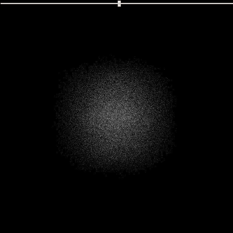
ok this was a long explanation, time to do something with it, the above will probably look somehow like this (click for live version):
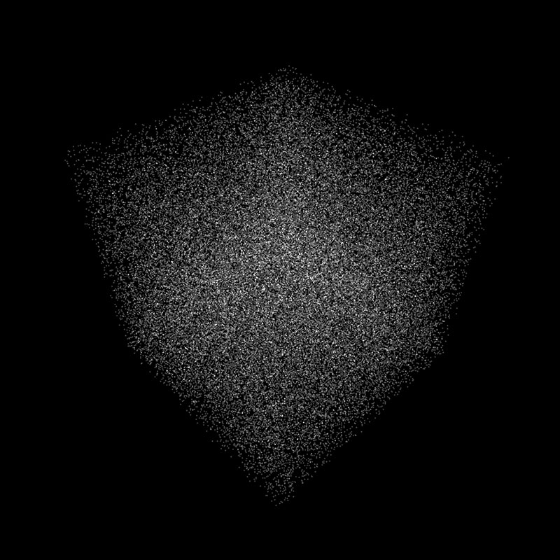
which is a bit dry I’ll admit, but at least it works :)
the benefit of this system is its ability to support lots of particles, I mean lots of them, while preserving a rather light memory footprint. the above uses a 256^2 texture or 65536 particles, 512^2 = 262144, 1024^2 = 1048576 etc…. and as many vertices which is often more than what is needed to display …well anything (imagine a mesh with 1+ Million vertices).
on the other hand particles often cause buffer overdraw which can slow down the render a lot if you render many particles on the same location for instance.
it’s trivial to create random or geometric position buffers, it’s straight forward to display an image of course (vertex position = normalized pixel position + elevation), it’s easy to create buffer describing 3D objects as we don’t need the connection information (the faces) and as we shall see, it’s also easy to animate this massive amount of particles.
let’s start with a random buffer:
|
1 2 3 4 5 6 7 8 9 10 11 12 13 |
//returns an array of random 3D coordinates function getRandomData( width, height, size ){ var len = width * height * 3; var data = new Float32Array( len ); while( len-- )data[len] = ( Math.random() * 2 - 1 ) * size ; return data; } //then you convert it to a Data texture: var data = getRandomData( width, height, 256 ); var positions = new THREE.DataTexture( data, width, height, THREE.RGBFormat, THREE.FloatType ); positions.needsUpdate = true; |
this is what I used for the first demo not very useful apart from debug, an image is a touch more interesting, how would we do that?
an image is a grid of values (pixels) so given an image, its width, height and an arbitrary elevation, the buffer creation goes as follow:
|
1 2 3 4 5 6 7 8 9 10 11 12 13 14 15 16 17 18 19 20 |
function getImage( img, width, height, elevation ){ var ctx = getContext( null, width, height ); ctx.drawImage(img, 0, 0); var imgData = ctx.getImageData(0,0,width,height); var iData = imgData.data; var l = (width * height ); var data = new Float32Array( l * 3 ); for ( var i = 0; i < l; i++ ) { var i3 = i * 3; var i4 = i * 4; data[ i3 ] = ( ( i % width ) / width -.5 ) * width; data[ i3 + 1 ] = ( iData[i4] / 0xFF * 0.299 +iData[i4+1]/0xFF * 0.587 + iData[i4+2] / 0xFF * 0.114 ) * elevation; data[ i3 + 2 ] = ( ( i / width ) / height -.5 ) * height; } return data; } |
the getContext() method creates a 2D context to access the image’s pixels values and the loooooong line computes the greyscale value for that pixel.
which should give this (can’t view online because of CORS restrictions, it’s on the repo though):
thanks to @makc for pointing out in the comments that images need a crossOrigin, in this case, img.crossOrigin = “anonymous”; solved the problem, so enjoy the live demo :)
it uses this 256 * 256 greyscale image:

loading a mesh is even easier:
|
1 2 3 4 5 6 7 8 9 10 11 12 13 |
function parseMesh(g){ var vertices = g.vertices; var total = vertices.length; var size = parseInt( Math.sqrt( total * 3 ) + .5 ); var data = new Float32Array( size*size*3 ); for( var i = 0; i < total; i++ ) { data[i * 3] = vertices[i].x; data[i * 3 + 1] = vertices[i].y; data[i * 3 + 2] = vertices[i].z; } return data; } |
the method takes the geometry of the loaded mesh and the trick here is to determine the size of the texture from the amount of vertices. this total is simply the square root of the vertices count.
click the picture for a live version
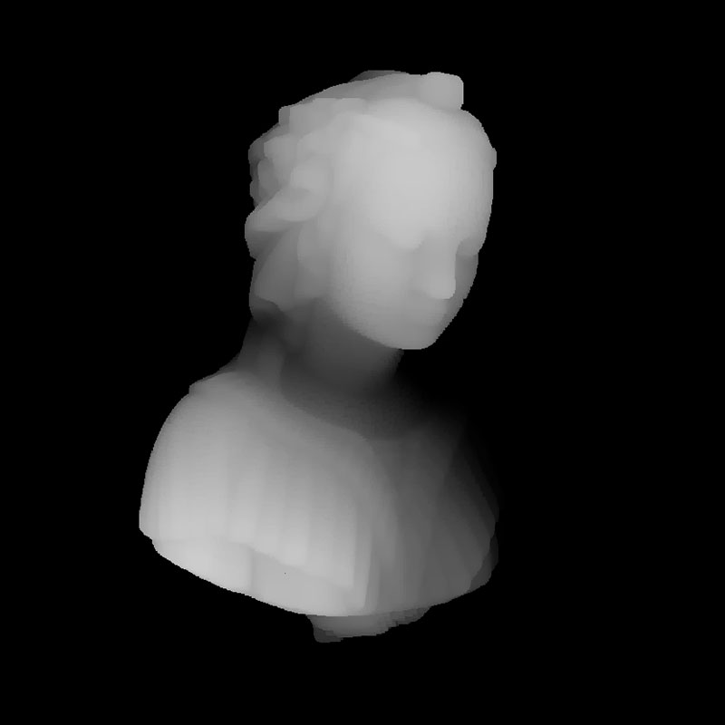
in the render shader, I compute the depth and the size of the particles is indexed on it which gives the illusion of faces but those are only particles (47516 particles, less than the first example).
what about animation?
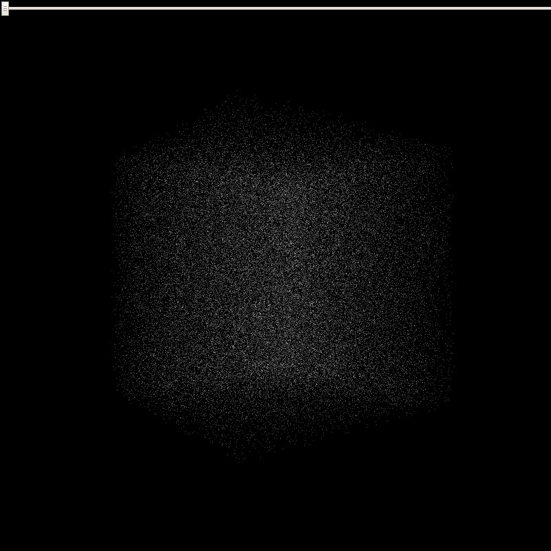
say we want to morph a cube into a sphere, first we need a sphere:
|
1 2 3 4 5 6 7 8 9 10 11 12 13 14 15 16 17 18 19 20 21 22 |
//returns a Float32Array buffer of spherical 3D points function getPoint(v,size) { v.x = Math.random() * 2 - 1 ; v.y = Math.random() * 2 - 1 ; v.z = Math.random() * 2 - 1 ; if(v.length()>1)return getPoint(v,size); return v.normalize().multiplyScalar(size); } function getSphere( count, size ){ var len = count * 3; var data = new Float32Array( len ); var p = new THREE.Vector3(); for( var i = 0; i < len; i+=3 ) { getPoint( p, size ); data[ i ] = p.x; data[ i + 1 ] = p.y; data[ i + 2 ] = p.z; } return data; } |
note that it uses the “discard” approach ; a point is generated randomly in the range [-1,1] and if it’s length > 1, it’s discarded. it is quite inefficient but prevents points from being stuck in the corners of a normalized cube. there’s also an exact way to prevent this problem that goes:
|
1 2 3 4 5 6 7 8 9 10 11 12 13 14 15 16 17 18 |
Math.cbrt = Math.cbrt || function(x) { var y = Math.pow(Math.abs(x), 1/3); return x < 0 ? -y : y; }; function getPoint(v,size) { var phi = Math.random() * 2 * Math.PI; var costheta = Math.random() * 2 -1; var u = Math.random(); var theta = Math.acos( costheta ); var r = size * Math.cbrt( u ); v.x = r * Math.sin( theta) * Math.cos( phi ); v.y = r * Math.sin( theta) * Math.sin( phi ); v.z = r * Math.cos( theta ); return v; } |
it needs cubic roots and involves more computations so all in all the discard method is not that bad and easier to understand (for people like me at least).
now back to morphing, the way to go is to create 2 DataTextures, one for the cube, one for the sphere and pass them to the simulation shader. the simulation shader will perform the animation between the 2 and render the result to the RenderTarget. then the render target will be used to draw the particles.
|
1 2 3 4 5 6 7 8 9 10 11 12 13 14 15 16 17 18 19 20 21 |
//first model var dataA = getRandomData( width, height, 256 ); var textureA = new THREE.DataTexture( dataA, width, height, THREE.RGBFormat, THREE.FloatType, THREE.DEFAULT_MAPPING, THREE.RepeatWrapping, THREE.RepeatWrapping ); textureA.needsUpdate = true; //second model var dataB = getSphere( width * height, 128 ); var textureB = new THREE.DataTexture( dataB, width, height, THREE.RGBFormat, THREE.FloatType, THREE.DEFAULT_MAPPING, THREE.RepeatWrapping, THREE.RepeatWrapping ); textureB.needsUpdate = true; simulationShader = new THREE.ShaderMaterial({ uniforms: { textureA: { type: "t", value: textureA }, textureB: { type: "t", value: textureB }, timer: { type: "f", value: 0} }, vertexShader: ShaderLoader.get( "simulation_vs"), fragmentShader: ShaderLoader.get( "simulation_fs") }); |
the simulation’s fragment shader is a bit more complex:
|
1 2 3 4 5 6 7 8 9 10 11 12 13 14 15 16 17 18 19 |
// simulation uniform sampler2D textureA; uniform sampler2D textureB; uniform float timer; varying vec2 vUv; void main() { //origin vec3 origin = texture2D( textureA, vUv ).xyz; //destination vec3 destination = texture2D( textureB, vUv ).xyz; //lerp vec3 pos = mix( origin, destination, timer ); gl_FragColor = vec4( pos,1.0 ); } |
that wasn’t too scary right? we have our 2 DataTextures (the cube and the sphere) passed to the simulation material along with a timer value which is a float in the range [0,1]. we sample the coordinates of the first model, store them in origin, the coordinates of the second model, store them in destination then use the mix(a,b, T) to blend between the two.
here’s a preview of the timer value being set at 0, 0.5 and 1:
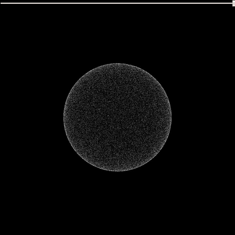
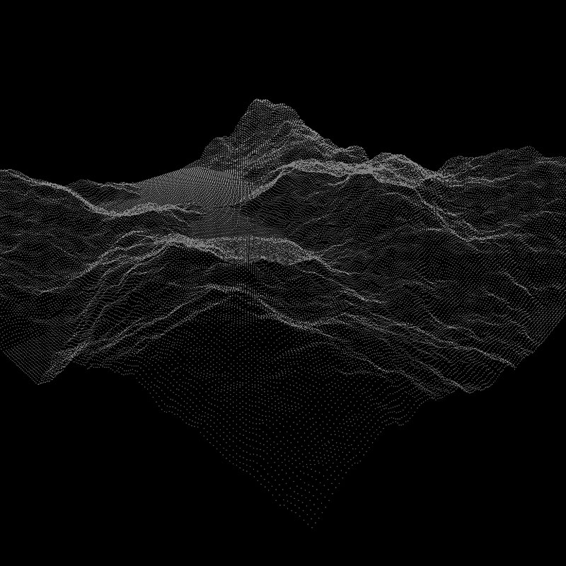
of course we can create more sophisticated animations, the idea is the same, anything that should alter the particles’ positions will happen in the simulation shader.
for instance this uses a curl noise to move particles around:
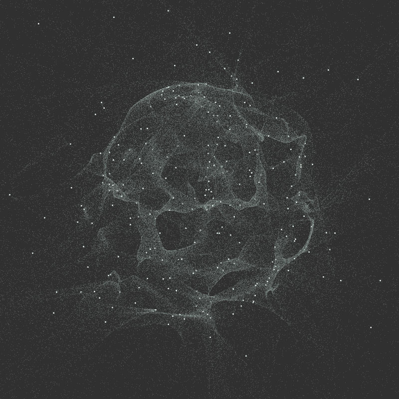
the size is set like this:
|
1 |
gl_PointSize = size = ( step( 1. - ( 1. / 512. ), position.x ) ) * pointSize; |
it reads, if the current “uv.x” is lower than 0,998046875, it’s a small particle, otherwise it’s big. if you’re interested in the simulation shader, it’s here, I don’t think it’s an example of good practices though.
to wrap it up, this technique allows to easily control insane amounts of particles, it is well supported (as compared to when I started using it at least) and – when using smaller texture sizes – it performs relatively well on most platforms ; usually GPUs optimize nearby texture sampling, which is what the FBO is based on.
I’ll leave you here, all the sources are on github.
enjoy
> (can’t view online because of CORS restrictions, it’s on the repo though)
rawgit serves Access-Control-Allow-Origin:* it is probably that you do not specify crossOrigin in the code.
well hello there :) that was it !!
I’ve specified img.crossOrigin = “anonymous” and it works, good to know :)
updated the article, thanks a bunch!
but more easily you could just push gh-pages branch and it will get official github.io url where you don’t have to deal with cross-domain stuff.
and I’m too lazy & disorganized to do this (trust me I tried ^^)
Thank you for your clear explanations.
However I can’t run your (and mr doobs and blursplines) examples. I am running on a Intel Mobile graphics card and it is likely that FBO is not supported there, although the WebGL checks should speak for it.
I am running into those errors:
[GroupMarkerNotSet(crbug.com/242999)!:E85E60BA1C240000]GL ERROR :GL_INVALID_FRAMEBUFFER_OPERATION : glClear: framebuffer incomplete (clear)
noise.html:1 [GroupMarkerNotSet(crbug.com/242999)!:E85E60BA1C240000]GL ERROR :GL_INVALID_FRAMEBUFFER_OPERATION : glDrawArrays: framebuffer incomplete (clear)
Maybe you know anything about it.
Thx again for explaining things!
I believe this is where WebGL falls short ; the Hardware specifics … I wouldn’t recommend using this on mobile devices anyway ; you’re not the gl.MAX_VERTEX_TEXTURE_IMAGE_UNITS maybe forbidden, or worst the Float Textures.
for your problem I don’t know, it seems to come from the RTT, maybe having a look at how to get a render to texture to work might help.
ok i fixed the problem :)
the THREE.DataTexture needs to be defined as THREE.RGBAFormat (not THREE.RGBFormat), so that it works on Intel Mobile Chips. I found out because mrdoobs FBO examples worked where these did not. So I compared the code and tada.
now I can play with FBOs on my cheap intel gpu as well :) beautiful!
Hi,
We see the phrase “framebuffer incomplete” in the error message. For this code, it indicates that you are unable to write floating point values into the frame buffer. The OES_texture_float extension, which the code checks, only indicates that you can create, and that the shaders can read floating point textures, not that the shaders can write to those textures.
To determine if the texture is writable, you have to setup the rendering pipeline, and do a CheckFramebufferStatus check. Perhaps more details than you want, but I have some notes on working around issues with floating point textures: http://www.vizitsolutions.com/portfolio/webgl/gpgpu/speedBumps.html
Also, for OpenGL ES, which WebGL is built on, reading textures in the vertex shader is optional, so this will trip up a lot of mobile graphics cards.
Hello Nico !
Glad to see you finally have some fun with shaders ;)
You should consider the fact to create the triangles directly inside the vertex-shader, based on 3 constants located in the shader ( defined once for all) representing the 3 vertex of a triangle.
Then you only need the position of your particle (the center of your “shader-triangle”) in your VBO and then you can put much more data in it ! :)
I posted an example showing how I use to do in the processing-forum
The GLSL code should work in WebGL without any modification.
https://forum.processing.org/two/discussion/8855/how-to-draw-millions-of-points-efficiently-in-processing
hey, thanks for passing by :)
this uses GL.POINTS instead of GL.TRIANGLES. if we use triangels, we’ll need to triple the vertex count (like in your example).
it’s a trade off ; GL.POINTS will perform faster with small point size (less data to process, less overdraw) but will slow dosn terribly when the point size gets bigger.
if the idea is to work with bigger surfaces, then your approach is the way to go :)
on a side note, using .5’s gives an isoceles triangle, an equilateral triangle (of circumradius 1) is defined like: ( 0, -1 ),( 0.8660254, 0.5 ),( -0.8660254, 0.5 )
Hey Im just starting to explore Webgl and Glsl and its really blowing my mind, but I had a question!
Is it possible to somehow connect the particles? To get this type of look: http://www.creativeapplications.net/wp-content/uploads/2011/05/alvin_part05.png
And if it is what would be the approach to creating this type of look
Thanks in advance and thank you for this post!!!
hey, thanks for your kind words :)
short answer: no, at least not directly. There are different primitives to draw with in WebGL, one of which is POINT and will draw particles (what we do here), to draw lines, you’ll need to use other primitives like: LINES, LINE_STRIP & LINE_LOOP (see https://www.khronos.org/files/webgl/webgl-reference-card-1_0.pdf).
the idea would be to draw a set of lines then draw the particles on top of it. looks easy enough but it requires a piece of information you don’t have in the particle system: connectivity ; indeed to draw lines, you need to know which points to connect. Over more, the picture you linked looks like a “node garden” (or a Force Directed Graph), it’s an emergent structure computed from the relative distance of nodes ; if they’re “close enough” draw a line, otherwise don’t. to compute this, you need to know where the nodes are before knowing if 2 nodes should be linked. this operation cannot be performed easily on the GPU (it would require a specific data structure and extra GPGPU steps) and given the amount of particles, computing on the CPU will require a lot of resources (and time).
this being said, you can use a grid or any mesh rendered with lines and use the same FBO technique to compute the vertices’ positions. I never did anything like this though, just a wild guess :)
Hi! This is one of the best articles on shaders i’ve read so far. Thanks for sharing, it’s immensely helpful and clear!!
I am trying to build an animation to morph meshes of any number of vertices. I have some extra vertices on one mesh that i need to hide. So, in the DataTexture i am using a THREE.RGBAFormat, instead of THREE.RGBFormat. Vertices are defined by a THREE.Vector4.
Now all vertices that are not needed have xyz values set to random and the alpha value set to 0 (hidden).
Everything works fine. But i cannot get that alpha value in the shaders.
If i add ‘transparent: true’ in the simulation shader, I get a strange behaviour: all the particles with alpha zero get scaled to position 0! And their alpha is still 1.
This is my simulation fragment shader:
void main() {
vec4 origin = texture2D( textureA, vUv ).xyzw;
vec4 destination = texture2D( textureB, vUv ).xyzw;
vec4 pos = mix( origin, destination, timer );
gl_FragColor = vec4( pos.xyz, pos.w );
}
And in the render shaders i added a varying containing to pass the alpha value to the fragment shader. Any idea why it does not work and it scales the positions?
(ignore this if it’s too confusing, sorry :)
Found the solution already and works great.
Just use RGBAFormat (instead of RGBFormat) in the FBO class: in the options of the rtt (WebGLRenderTarget).
As simple as that :)
I’m trying to do the same, but my code is not working and I can’t pinpoint the issue. Do you still have all the code for this by any chance? It would be immensely helpful. I am trying to store an additional value for the color of each particle.
Or do you remember what else you had to do for this to work? Does the simulation VS needs changes too? I changed the render vertices to be a BufferAttribute(vertices, 4), but does the simulation position need to be a size 4 vector?
Thank you so much
Hey Nico,
Really cool project. I have this bookmarked for a few months now because i was trying to create something similar but because i am new to THREE and WEBGL i was not able to follow your instructions.
In the meantime i have found this example http://www.pshkvsky.com/gif2code/animation-13/ which i was able to follow. But it doesn’t work as smoothly as yours does. I guess the ‘raycasting’ metehod is too inefficient for defining points on a mesh.
I am looking for a better way to form shapes (loaded 3d object) out of particles in THREE.js. Do you have some time to explain that in more details?
You can find my current progres here http://www.sander-wilbrink.com/ but again, i am quite new to webgl and most of this code comes from http://www.pshkvsky.com (credits where credits are due of course)
PS: have you seen this awsome example? https://xmas.astral.de/#
Kind regards
Sander
hi,
sorry I didn’t see this comment earlier :)
your question boils down to knwoing where to place particles on a mesh.
as far as the astral website is concerned, it’s very nicely done! :) they probably used a depth sensor (kincet, leap motion, 3D camera…) to scan the faces and assign the size of the dots depending on how close the particle is from the ‘camera’. it’s possible to use photogrammetry too but it would be somehow overkill and less efficient in this case :)
if you have a mesh, the raycasting – though very slow as you mentioned – could be the way to go ; shoot X random rays at the mesh, store the intersections, rotate the mesh a bit, repeat. this is basically what the kinect (or any LIDAR device) does. then you obtain a series of points on the surface of the mesh.
if you have a mesh and only need points onn the surface, you can use the geometry’s ‘faces’ and radomly distribute points on the face. this is fairly trivial. the trick here is to use a ratio based on the area of the triangles to set the amount of random particles to create for each face.
hope this will help you go on, thanks for passing by :)
Hi I’m Johan!
Your particle effect is really cool !!!!
But when I try to view it on my phone, three.js throw an warning that it does not support “EXT_frag_depth”.And the effect of the particles did not appear.
But I did not see “gl_FragDepthEXT” in your glsl code.
I am very confused about this.
ps: The performance particles on phone is very important and I really want to use your technology on the phone.
Hi! Admiring this article! Good explanation!!
I tried to follow your steps and what you did and have one question.
Am i right, that what is done in the article may be done without FBO approach actually?
We can just compute that same curl noise in vertex shader in one pass. Based on some geometry
positionsattribute (your sphere) and time uniform?I mean, of course, FBO can be extended by adding velocities texture and etc. But does this exact animation in article benefit from it?
Again, thank you for this article, it has been my first step into this type of animations!
Thanks so much !
This was really useful for learning how to deal with a lot of particles, thank you so much!
What would be the most efficient way to handle dynamic color changes? E.g. constantly changing colors based on their previous colour, evolving into new colours all the time. Would it need another pass to store and update the RGB values of the particles or use the same pass?
Cheers!
hey,
thanks :)
I guess you found out by yourself but for the record, unless the color is based on the position, you’ll need a second texture to encode the color state. now if it’s a color cycle, maybe using a time uniform + a delta (stored as an attribute) can be enough. not sure what was best for your use case…
Hi Youpi
I really found this work awesome I was trying to incorporate it into a modern Next.Js project but kept on hitting some stumbling blocks. Is there anything like this with react-three-fiber to modernise your work I did try but its quite difficult without yourself :) Would love to hear back from you on your thoughts?
I’m getting the Uncaught Error: floating textures are not supported
hey,
this means that either your device does not support float textures ( the Samsung S series is famous for that ) or the extension test fails.
if your device does not support float textures, this won’t work and unfortunately there’s not much you can do.
Hi youpi, thank you, your article really helps me to understand this. I wonder if we can have multiple models in it, if we are allowed to have multiple models in it, how do I morph them in the simulation fragment shader? thank you
hey,
well if you managed to morph between 2 objects (the cube and sphere in the article), adding new models follow the same logic ; you’ll need to convert a model into a datatexture, pass it to the shader and blend between datatextures with uniforms.
the trick is that all the datatextures must have the same size so your models should ideally have the same vertex count or you must find a way to add vertices to the lesser defined models so that they all have th esame count.
not sure if it’s clear but I hope it helps.
I am trying to copy the code. I used Threejs 159 version, but it was not successful. I don’t know why
hey, this is very old code so if you have to start somewhere, I’d recommend using Mario’s code https://github.com/marioecg/gpu-party/ as it’s more likely to work with recent versions of three :)
I clones the repo and i works totally fine. I tried integrating the noise.html file with react js. I did all i could. Installed three js using npm. Copied the fbo script, copied the noise.html script.
The issue I faced was float gl oes texture not supported. However if that was the case how did it work when i cloned the repo for the first time…
All suggestions welcomed
If you are using RGBA instead of RGB then there needs to be 4 fields instead of 3. The changes in order to accomodate the RGBA should be len = size * 4 instead of size * 3. Also change the texture loop accordingly setting up the ‘a’ values to 1.
Hello Nico,
This post is still very very relevant as it is still the best way to leverage GPGPU and three.js.
I’m not sure if you’ve tried when loading a mesh and passing the vertex color data from the loaded mech into the render material.
The fragment shader line
gl_FragColor = vec4( vec3( 1. ), .25 );
Which is part of the renderMaterial (ShaderMaterial) “pass”. Is what defines the color that is rendered.
I am able to access the my color data of the loaded mesh via
geometry.attributes.color.array (returns a Float32Array).
I tried using the following:
// Create the particles geometry
const geometry = new THREE.BufferGeometry();
BufferGeometry.setAttribute(“position”, new THREE.BufferAttribute(vertices, 3));
BufferGeometry.setAttribute(‘color’, new THREE.BufferAttribute(this.activeGeometry.attributes.color.array,4));
The above is not working
I understand how to change all the gl_FragColor via a color/values uniforms.
But unable to make the color data from the loaded geometry….
thanks
Adding color to the parseMesh
function parseMesh(g){
var vertices = g.vertices;
var total = vertices.length;
var size = parseInt( Math.sqrt( total * 3 ) + .5 );
var data = new Float32Array( size*size*3 );
var color_data = new Float32Array( size*size*3 );
for( var i = 0; i < total; i++ ) {
data[i * 3] = vertices[i].x;
data[i * 3 + 1] = vertices[i].y;
data[i * 3 + 2] = vertices[i].z;
color_data[i * 3] = colors[i].x;
color_data[i * 3 + 1] = colors[i].y;
color_data[i * 3 + 2] = colors[i].z;
}
return data;
}
Hello Nico! Your atricle has helped create a slew of examples. But unfortunately nobody online has been able to add color based of a loaded mesh correctly.
When say loading a PLY file vertex position is located on the attributes.position.array.
Colors of each vertex (point) will be in attributes.color.array
but colors don't match the vertex point… could you provide any feedback on what may be causing the mismatch.
hey, thanks for your kind words and sorry for the late reply
you’re almost there!
as you guessed already, you need to add a color “attribute” which is what you’re doing with :
BufferGeometry.setAttribute(‘color’, new THREE.BufferAttribute(this.activeGeometry.attributes.color.array,4));
just that BufferGeometry should be ‘geometry’ (an instance of the BufferGeometry class)
also make sure that your color is a vec4 or if it’s a vec3 , change the ‘4’ at the end of your line should be a 3 (this may cause a mismatch).
then you’ll need to add some code to handle the color attribute in the render shaders, I created a PR on Mario’s repo so you can check the changes in both shaders here : https://github.com/marioecg/gpu-party/pull/2/commits/d92ff937f2a1665c76073c8fa5b172e0df1677cc#diff-6c2c86be715ba34adb5b6c0ff7dd46a49d3559963f8095fcdee37266e8e3e019
basically in the vertex shader add:
attribute vec3 color; // <= make sure the color is a vec3 or change vec3 to vec4 varying vec3 vColor;// varying will pass the color to the fragment void main() { vColor = color;// assign the attribute color before passing to the fragment and in the fragmaent shader: varying vec3 vColor;// receive the color void main() { gl_FragColor = vec4(vColor, 1.);// use the color to rende the particle hope this makes sense cheers