a month ago, for no specific reason, I decided to implement a 2D top-down visibility algorithm. I always found the output beautiful both graphically & conceptually yet, as I don’t make games, I never tacckled it.
visibility algorithms are often used to simulate lights ; to determine which areas of a space are enlightened and which lie in the shadow but they can also be used to power an AI ; make an agent aware of its whereabouts.
if you’re after a robust solution or just curious, I’d suggest you open one of those links:
- Amit Patel’s articles and resources
- this article by Nicky Case because it looks good
- this js implementation by Byron Knoll visibility-polygon.js
- the Game Mechanic Explorer addressed the topic in a clear & concise manner
also, if you only need the graphic data, you might be interested in GPU solutions ; this article explains the shader based approach. and if you’re more into the game-making thing, the beamcasting approach seems very efficient, especially as the triangular structure offers many advantages to handle the game’s logic.
I know you’ll find something that suits your needs along with valuable insights.
the algorithm
as mentioned above, I’m only interested in the algorithm itself so this article gathers a couple of thoughts on the topic, some sample animations and some JavaScript code.
I wanted to keep the algorithm topology-agnostic ; it should work on any series of segments (edges) & make as few assumptions about the data structure as possible. in real life, one would probably adapt what follows to perform faster ; for instance re-using the edges instead of rebuilding them each time might be a good start.
I kept the examples intentionally unoptimized here, a naive pseudo-code goes as follow:
- create edges
- store them in a an array
- compute & store the edge’s start & end angles
- sort the angles in ascending order
- for each angle of the angles’ list
- cast a ray from the light source at this angle
- with all the edges
- if the edge contains the angle
- compute & store the closest intersection of this ray with the edge
- push the closest intersection point to the solution
which translated into (a somewhat obfuscated) code gives:
|
1 2 3 4 5 6 7 8 9 10 11 12 13 14 15 16 17 18 19 20 21 22 23 24 25 26 27 28 29 30 31 32 33 34 35 36 37 38 39 40 41 42 43 44 45 46 47 48 49 50 51 52 53 54 55 56 57 58 59 |
function compute( points, light ) { //local variables var solution = [], edge = null, edges = [], angles = []; var API2 = 0, A = 0, B = 0, C = 0, closest = null; //start points.forEach( function( p0, i, a ) { // 1 - create edges edge = new Edge( p0, a[ ( i+1 ) % a.length ], light ); // 2 - store them in an array edges.push( edge ); // 3 - compute & store the edge’s angles // this is done inside the Edge object // and stored as edge.start / edge.end if( angles.indexOf( edge.start ) == -1 ) angles.push( edge.start ); if( angles.indexOf( edge.end ) == -1 ) angles.push( edge.end ); } ); // 4 - sort the angles in ascending order angles.sort( function(a,b){ return a - b; } ); // 5 - for each angle of the angles’ list angles.forEach( function( angle ) { if( angle >= angles[0] + PI2 ) return;//we've done a complete 360° > quit // 6 - cast a ray from the light source at that angle API2 = angle + PI2; A = -Math.cos( angle ); B = Math.sin( angle ); C = light.x * ( light.y + B ) - light.y * ( light.x - A ); // 7 - with all the edges closest = null; edges.forEach( function( edge ) { // 8 - if the edge contains the angle if( ( angle < edge.start || angle > edge.end ) && ( API2 < edge.start || API2 > edge.end ))return; // 9 - compute the intersection of this ray with this edge var pp = project( light, A,B,C,edge.D,edge.E,edge.F); // & store this intersection point if it is closer to the light source if( closest == null ) closest = pp; else if( closest.distance > pp.distance ) closest = pp; } ); // 10 - push the closest intersection point to the solution if( closest != null ) solution.push( closest ); } ); return solution; } |
now if you suspect some trickery here, you’re right. this snippet alone won’t do much for it needs 2 data-holders (Point & Edge) along with some methods (angle, distance, project) to work.
the Point object simply stores a X, Y coordinates & a distance value, now the Edge object is slightly more tricky as it needs to ensure the points are properly oriented (CW).
|
1 2 3 4 5 6 7 8 9 10 11 12 13 14 15 16 17 18 19 20 21 22 23 24 25 26 27 28 29 30 31 32 33 34 35 36 37 38 39 40 41 42 43 44 45 46 |
/** * Edge is a dataHolder that keeps references to 2 points * @param p0 start of the edge * @param p1 end of the edge * @param light the light source */ var Edge = function( p0, p1, light ) { //compute: // A: the angle from the light source to point 0 var a = ( angle( light, p0 ) + PI ); // B: the angle from the light source to point 1 var b = ( angle( light, p1 ) + PI ); // span: the angle difference between A & B var span = Math.atan2( Math.sin( b - a ), Math.cos( b - a ) ); //the winding of the edge: its orientation // if A + span is smaller than A, the edge is oriented Counter ClockWise var CW = a < a + span; //if the angle is sorted ClockWise, nothing to do if( CW ) { this.p0 = p0; this.p1 = p1; this.start = a; this.end = a + span; } //otherwise, flip the edge else { this.p0 = p1; this.p1 = p0; this.start = b; this.end = b - span; } // & finally these values are precomputed to make projections faster this.D = this.p0.x - this.p1.x; this.E = this.p1.y - this.p0.y; this.F = this.p0.x * this.p1.y - this.p0.y * this.p1.x; }; |
the orientation is important because the angles are sorted in ascending order so the scanline rotates clockwise & if an edge is oriented CounterClockwise (CCW), the computation will fail.
angle & distance methods are fairly easy to find, so here is the projection method:
|
1 2 3 4 5 6 7 8 9 10 11 12 13 14 15 16 17 18 19 |
/** * projection method * @returns {Point} */ function project( light, A, B, C, D, E, F ) { var denominator = 1 / ( B * D - E * A ); //this is the projected point var out = new Point(); out.x = ( C * D - F * A ) * denominator; out.y = ( F * B - C * E ) * denominator; out.distance = squareDistance( light, out ); return out; } |
I used the projection method found here & precomputed most of the values: A,B,C represent the ray & are set on step 6 of the algorithm, D, E, F represent the Edge and are computed during the edge’s instantiation (see Edge Object). note that we can use Square Distance (faster) instead of the actual distance as we only need to know if a value is smaller than another. below is a little demo staging a caribou
naive approach fullscreen
it works nicely when the light is inside the shape, yet some major flaws happen
- all edges are computed which is not a good idea
- the algorithm does not make a difference between the inside / outside
- from “outside”, the visibility polygon is not closed properly
- some mid-edge projections are lost as the scanline moves forward
in other words, it sucks.
which edges?
the first step is to determine which edges to process. we need to process an edge only if it is potentially visible from the light source. this is achieved by computing the dot product of the edge’s normal vector & the vector going from the light source towards one of the edge’s vertices. if the result is negative, the vectors are pointing in opposite directions meaning the edge is “facing” the light source & needs to be processed.
this is the code you need:
|
1 2 3 4 5 6 7 8 9 10 11 12 13 14 15 16 17 18 19 20 21 22 23 24 25 26 27 28 29 30 31 32 33 34 |
function normalize( point ) { var length = Math.sqrt( point.x * point.x + point.y * point.y ); point.x /= length; point.y /= length; return point; } function normal( p0, p1 ) { return new Point( -( p0.y - p1.y ), ( p0.x - p1.x ) ); } function dotProduct( p0, p1 ) { return ( p0.x * p1.x + p0.y * p1.y ); } // p0 / p1 are the two edge's ends // light is the light source // dir is a temporary vector from one end of the edge // to the light source var dir = new Point(); dir.x = p0.x - light.x; dir.y = p0.y - light.y; var norm = normalize( normal( p0, p1 ) ); //edge is visible if( dotProduct( norm, dir ) < 0 ) { //visible edge code here } |
statistically, this removes 50% of the computations. note that I said as few assumptions as possible concerning the edges but this is a strong one ; I assume that edges are opaque on both sides. by using a more sophisticated edge data structure, we could specify which side is visible or have one-sided walls ( like a stainless mirror ).
a nice (& necessary) addition is the visibility range ; beyond a given distance from the light source, we don’t have to compute anything.
by adding a simple distance check to the previous test, we can decimate the potentially visible edges’ list further.
|
1 2 3 4 5 6 7 8 9 10 11 12 13 14 15 16 |
function squareDistance( a,b ) { return ( a.x - b.x ) * ( a.x - b.x ) + ( a.y - b.y ) * ( a.y - b.y ); } [...] //the light's range var range = 200; //using square distances saves some square roots computations var square_range = range * range; if( squareDistance( p0, light ) > square_range && squareDistance( p1, light ) > square_range ) { // both ends of this edge are too far, no need to process continue; } |
overmore, if we consider the edges as walls & we know that we can have closed shapes, an interesting test can be performed before actually processing anything to determine whether or not a polygon contains the light source & eventually stop the computation there. in my previous article, I’ve shown a method that does this.
here’s a live demo:
potential visibility fullscreen
move around to see the potentially visible edges (blue) click & drag to use the visibility range, when the shape turns grey, it means that the shape contains the light so nothing is computed.
when clicked, the pink edges are out of range & don’t need to be processed which leaves us only with the blue edges. I’ve displayed the decimation ratio that indicates how much of the original edges are valid and need to be processed.
closing the visibility polygon
the visibility range is a nice addition yet it induces a greater problem ; how to close the Visibility Polygon.
the simple solution is to enclose all the polygons inside a bounding polygon (usually a quadrilateral) & use infinite rays ; this way we are certain that the rays will hit something… some time.
in the next example, I’ve added a series of 4 (yellow), 8 (red) & 60(blue) edges forming a circle around the light.
I also perform the tests described above so when running, only the visible edges within the light range are being processed. this should run much faster than the naive approach (roughly twice).
here’s the result:
before starting the animation, you should see the outlines of the visible polygons.
even though it works, this is not a very elegant solution ; we have to create extra geometry or we’ll lose the benefit of a visibility range. in the case of AI, the agents would have an infinite line of sight, in the case of graphics, the light would flood offscreen which is not the expected result. overmore, this approach doesn’t solve the mid-edge projection issue & the precision of the boundaries depends on the number of edges added (the edge count is discrete as opposed to continuous arcs).
I had the intuition that the problem could boil down to determining when a ray would switch between distances from the light source. indeed if we convert all cartesian coordinates to polar coordinates, we get the 2 values we need to solve the algorithm:
- the angles at which we should project rays
- the distances from each point to the light source
as it’s not a trivial concept to understand, here’s a demo of polarization
polar fullscreen
move your mouse around, you’ll see the arcs described by the edges’ start and end angles projected on the visibility range around the mouse.
the important bit here is what happens at the bottom where all the angles are represented as vertical lines and all the edges as segments.
before going further, computing the edge’s projection against the visibility circle allows for a nifty trick ; instead of computing the visible polygon, what if we compute the invisible polygon?
instead of casting light, why not casting shadows?
here’s how the code would go:
|
1 2 3 4 5 6 7 8 9 10 11 12 13 14 15 16 17 18 19 20 21 22 23 24 25 26 27 28 29 30 31 32 33 |
ctx.fillStyle = "rgba(0,0,0,.15);//15% opacity ctx.beginPath(); var dir = new Point(); for( var i =0; i < points.length; i++ ) { var p0 = points[ i ]; var p1 = points[ ( i+1 ) % points.length ]; //same old visibility test to spare computations dir.x = p0.x - light.x; dir.y = p0.y - light.y; var norm = normalize( normal( p0, p1 ) ); //edge is visible if( dotProduct( norm, dir ) <= 0 ) { edge = new Edge( p0, p1, light ); //this is the projection of the edge's ends on the visibility range var pp0 = new Point( light.x + Math.cos( edge.start ) * range, light.y + Math.sin( edge.start ) * range ); var pp1 = new Point( light.x + Math.cos( edge.end ) * range, light.y + Math.sin( edge.end ) * range ); ctx.moveTo( edge.p0.x, edge.p0.y); ctx.lineTo( edge.p1.x, edge.p1.y); ctx.lineTo( pp1.x, pp1.y ); ctx.lineTo( pp0.x, pp0.y ); } } ctx.fill(); |
& this would be the result (click maintain & drag):
note: you’ll need a big range for it to work as it is supposed to overflow the screen.
if the light source is too close from the edge, it will fail. as the edge’s end are projected on a huge circle, the closer you get to a wall, the closer the arc’s chord will be to the back of the wall. it’s still a fast and easy solution for graphics rendering of shadows.
back to the polar view, we saw it’s possible to consider the edges’ projections as angle-distance rather than X Y coordinates (polar coordinates vs cartesian coordinates).
to solve the problem in the polar space, we have to change the approach a bit. the scanline would move from left to right & the light would cast a ray from the top towards the bottom. the picture below sums up the cases we need to solve.
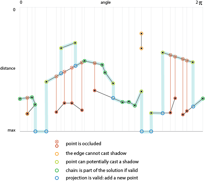
we’re after the thick blue line.
the code remains the same as before but instead of systematically picking the closest intersection, we’ll have to perform some extra tests depending on the nature of the point being processed & for this we need…
a less stupid data structure
a less stupid Point
|
1 2 3 4 5 6 7 8 9 10 11 12 13 14 15 16 17 |
var EdgePoint = function( x, y, angle, distance, light ) { this.x = x||0; this.y = y||0; this.angle = angle||0; this.distance = distance||0; this.A = -Math.cos( this.angle ); this.B = Math.sin( this.angle ); this.C = light.x * ( light.y + this.B ) - light.y * ( light.x - this.A ); this.edge = null; this.isChained = false; this.isArc = false; }; |
now the point is aware of the edge it belongs to, stores its angle and knows if it belongs to a chain or if it is the end of an edge. in addition, it computes the values (ABC) required to perform the projection test & can be flagged as an arc (see render method below).
a less stupid edge
|
1 2 3 4 5 6 7 8 9 10 11 12 13 14 15 16 17 18 19 20 21 22 23 24 25 26 27 28 29 |
var Edge = function() { this.p0 = null; this.p1 = null; this.a0 = 0; this.a1 = 0; this.init = function( p0, a0, d0, p1, a1, d1, light ) { a0 = ( a0 + PI2 ); a1 = ( a1 + PI2 ); this.p0 = new EdgePoint( p0.x, p0.y, a0, d0, light ); this.a0 = a0; this.p1 = new EdgePoint( p1.x, p1.y, a1, d1, light ); this.a1 = a1; this.D = this.p0.x - this.p1.x; this.E = this.p1.y - this.p0.y; this.F = this.p0.x * this.p1.y - this.p0.y * this.p1.x; this.p0.edge = this; this.p1.edge = this; }; }; |
it stores the two points, the two angles & precomutes the projection value D,E,F.
another thing we have to determine is whether or not a point is occluded ; indeed if a point is completely hidden behind an edge, it cannot belong to the solution.
during the projection loop, I’ve added an occluded boolean that is set to false for each point & switches to true if the point’s projection is closer to the light source than the point itself (those are the red crosses the picture above).
with this less stupid data structure, we can refine the tests after finding the closest point:
|
1 2 3 4 5 6 7 8 9 10 11 12 13 14 15 16 17 18 19 20 21 22 23 24 25 26 27 28 29 30 |
if( !occluded ) { //if the point doesn't belong to a chain if( !p.isChained ) { // and was not projected on any other segment if( closest == null ) { // it belongs to the visibility range //we have to create this point closest = polarToCartesian( p.angle, range, light ); closest.angle = A; //and flag it as an arc closest.isArc = true; } if( p == p.edge.p0 )// if p is the start point of the edge { solution.push( closest, p ); } else // other wise p is the end point { solution.push( p, closest ); } } else { //the point belongs to a chain, add it solution.push( p ); } } |
when a point belongs to the visibility range, we need to create a point using the polarToCartesian() method. no black magic here either:
|
1 2 3 4 5 6 7 |
function polarToCartesian( angle, distance, origin ) { var out = new Point(); out.x = origin.x + Math.cos( angle ) * distance; out.y = origin.y + Math.sin( angle ) * distance; return out; } |
which gives us this glorious demo:
behold YE glorious fullscreen – here’s the source code
the source code is not the cleanest you can dream of but at least it is standalone.
another thing is that to properly close the the visibility polygon, we need to draw arcs. that’s where the EdgePoint.isArc comes to the rescue.
the arcs are always drawn between 2 points of the solution so the rendering method only needs to know when 2 consecutive points of the solution have their .isArc flag set to true & draw a sector (a.k.a. pie slice) otherwise draw a triangle.
|
1 2 3 4 5 6 7 8 9 10 11 12 13 14 15 16 17 18 19 20 21 22 |
var solution = compute( points, light, range ); context.beginPath(); for( i = 0; i < solution.length; i++ ) { context.moveTo( light.x, light.y ); p = solution[ i ]; n = solution[ ( i+1 ) % solution.length ]; if( p.isArc && n.isArc ) { context.arc( light.x, light.y, range, p.angle, n.angle, false ); } else { context.lineTo( p.x, p.y ); context.lineTo( n.x, n.y ); } context.lineTo( light.x, light.y ); } context.closePath(); context.fill(); |
this takes advantage of the way the Canvas API works : beginPath() opens a buffer of mixed instructions until the closePath() or a draw method is called. as our solution is guaranteed to be convex & to have a CW winding, we can iterate on the solution’s points linearly.
it’s pretty similar to having created the circular frame around the light with the notable difference that it doesn’t create extra geometry. unfortunately there are still some cases where it breaks ; the arcs are not drawn properly so the safest is still to use a bounding polygon.
penumbra
I tried to implement a penumbra (soft shadows) as described in this article but failed miserably.
the plan was simple, as we know when we render an arc, we should be able to draw an area that simulates the light fading away. to do this – as the shading is not linear – we need a texture like the one below:

(in photoshop, it’s a transparent “angle gradient” with a very small (<2%) opaque black span at both ends) so whenever we hit an arc, we translate the canvas at the location of the point before the arc point, rotate the canvas to orient it along this edge. then we set the texture as fill pattern & draw an arc of 45° (= PI / 4). the code:
|
1 2 3 4 5 6 7 8 9 10 11 12 13 14 15 16 17 18 19 20 21 22 23 24 25 26 27 28 29 30 31 32 33 34 35 36 37 38 39 40 41 42 43 44 45 46 47 48 49 50 51 52 53 54 55 56 |
var pid = 0, nid = 0, previous = null, next = null, dist = 0; for( i = 0; i < solution.length; i++ ) { p = solution[ i ]; n = solution[ ( i+1 ) % solution.length ]; if( p.isArc && n.isArc ) { //left shadow pid = ( i-1 ) < 0 ? solution.length - 1 : ( i - 1 ); previous = solution[ pid ]; dist = range - previous.distance; context.save(); context.translate( previous.x, previous.y ); context.rotate( p.angle - PI / 4 ); context.beginPath(); context.moveTo( 0,0 ); context.arc( 0,0, dist, 0, PI / 4, false ); context.lineTo( 0,0 ); context.closePath(); context.fill(); context.restore(); //right shadow nid = ( i+2 ) % solution.length; next = solution[ nid ]; dist = range - next.distance; context.save(); context.translate( next.x, next.y ); context.rotate( n.angle - PI / 4 ); context.beginPath(); context.moveTo( 0,0 ); context.arc( 0,0, dist, PI / 4, PI / 2, false ); context.lineTo( 0,0 ); context.closePath(); context.fill(); context.restore(); } } |
& here’s the result:
fullscreen – source – texture
there are flaws here too ; the self-projections are not taken into account ; it would mean we know which side fades in which direction. as we use a texture, it can’t be faded away along the edge’s axis like a radial gradient would so the length of the soft shadow depends on the texture itself.
holes
this basically relies on the way edges are built & oriented ; the same algorithm works with “compound” objects.
here’s a compound object for instance ; the eyes and the nose have a different orientation then the rest.
fullscreen – source
20 light sources are computed on click (might take some time…), sometimes the light lies within a “hole” & doesn’t spread around or is being blocked by the shape containing the “hole”.
I used 2 color palettes: canary & Hibiki note that the shapes are not being drawn at all ; it’s only made of light.
extending
along the way, I thought of a couple of extensions that could be done to improve the thing further
- various light shapes: I used only point lights but why not using a direction & an angle span to create a spot light? or a line that would emit light along its normals?
- translucency: if the ends of the edge know how much light they let through, they can affect the visibility range thus creating a cheap “translucency”
- caustics: as for translucency, caustics would bounce some of the light it recieives either outwards (reflection) or inwards(refraction)
- curves: I’m only using line/line intersections here but with a more clever data format & the appropriate intersection methods, it is possible to use curves (for instance using Kevin Lindsey’s intersection routines)
- handling the primitives such as circles or regular polygons separately ; there are “shortcuts” to perform the projections on those shapes
… the hidebehind?
I like all kinds of insects, chimeras, monsters (dragons seems trendy those days) & I often envision the algorithms as creatures with an autonomous life. I first read about the hidebehind in the Book of Imaginary Beings by Jorge Luis Borges. here’s a description of this creature ( wikipedia source )
[…] As its name suggests, the hidebehind is noted for its ability to conceal itself. When an observer attempts to look directly at it, the creature hides again behind an object or the observer and therefore can’t be directly seen […]
the hidebehind was a good match for what I was after: a creature that can’t be seen.
Wow this looks great!! Nice to read about the whole process. I once created such in actionscript, not shape but bitmap-based raycast. It could be a nice addition to also add an inversed shape with dark gradient. to suggest a bit of shadow.
http://blog.stroep.nl/2011/11/lights-and-shadows/
hey Mark thanks for your comment :)
I missed this article of yours, nice and clever, thanks!
I was after the geometric algorithm here – not only the graphics – in which case I think I would have used the “GPU approach” and done something in the way of what you describe in your article
as far as the inversed shape goes, I think drawing a circle of radius “range” counter clockwise at the end of the rendering loop should do the trick (wild guess here, not tried)
While playing with moose demo, as well as looking at your screenshots later, I do not quite understand why there is no light in its feet sometimes (e.g. http://i.imgur.com/wLAsnQK.png )
( thanks for passing by! :) ) this is what I described as “4 – some mid-egde projections are lost as the scanline moves forward” in the naive approach, only the closest candidate is being picked ; in that case, the point is closer to the light than its projection on the (foot’s) segment. this is a typical case where a point is the “end” of an edge and should be able to cast a projection that is located further from the light than the point itself. in the naive approach, this case is not handled ; only the closest projection is kept which causes this bug.
Amazing… as usual.
I will never be this good even if I got to do it all again :O
Will be cool with real time animation .
Can be used also like generators of sprites.
I don’t see a following area, why ? Fix that with feedly .
Good articles .