a short post about the marching squares algorithm, a technique mostly used to vectorize the outline of a binary image.
it’s a very well known & very well spread technique, I happened to have some spare time & the urge to do something graphic.
for a start let’s look at how things work.
the idea is to draw a shape through the edges of cells which vertices are “weighted” ( each point of the cell has a value ). in our case, we use an image to represent the cells’ grid ( an image is a grid of pixels ) & if we use a binary image (black & white, no greyscale), the weights are the colors of the pixels ( 0 or 1 ) . then we need a structuring element or kernel to scan our grid & find the outline.
the algorithm goes as follow:
- apply a threshold to the image to obtain a binary image
- find the first non transparent pixel
- position the kernel at this location
- while the kernel has not reached the starting location
- move the kernel around the shape
- store the new location
- if the number of iteration is too high, break
- else continue
the first step is fairly easy ; when you access the imageData of a given canvas, you can scan all the pixels’ components ( r,g,b or a ) & match them against a given value.
a good idea though is to reduce the image’s colors before performing the marching square process ; this can be done quite simply either beforehand by using a restricted palette or on the fly by applying a simple reduction algorithm like:
|
1 2 3 4 5 6 7 8 9 10 11 12 13 14 15 16 17 18 19 20 21 22 23 24 25 26 27 28 29 30 31 32 33 |
function segment( imageOrCanvas, steps ) { var w = imageOrCanvas.width; var h = imageOrCanvas.height; var canvas = document.createElement("canvas"); document.body.appendChild( canvas ); canvas.width = w; canvas.height = h; var context = canvas.getContext("2d"); context.fillStyle = "rgba(255,255,255,255)"; context.fillRect(0, 0, w, h); context.drawImage(imageOrCanvas, 0, 0 ); var imgData = context.getImageData(0, 0, w, h); var data = imgData.data; for( var i = 0; i < data.length; i += 4 ) { data[i] = parseInt(parseInt( ( data[i] / 0xFF ) * steps + .5 ) * ( 0xFF / steps ) ); data[i + 1] = parseInt(parseInt( ( data[i + 1] / 0xFF ) * steps + .5 ) * ( 0xFF / steps ) ); data[i + 2] = parseInt(parseInt( ( data[i + 2] / 0xFF ) * steps + .5 ) * ( 0xFF / steps ) ); } imgData.data = data; context.putImageData( imgData, 0, 0 ); } var img = document.getElementById( "me_gusta" ); segment( img, 16 ); segment( img, 8 ); segment( img, 1 ); |
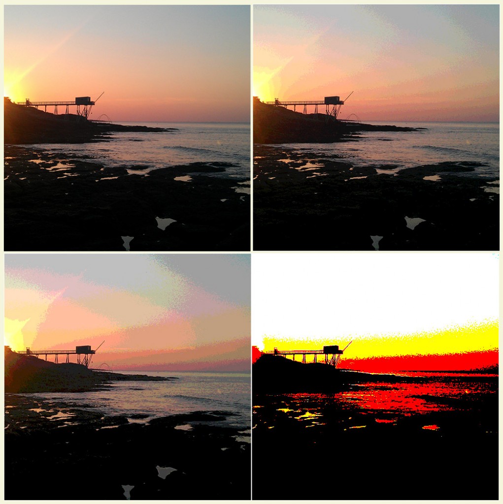
which will give you something like
the idea is simple, for each component of the color, first normalize it ( data[ X ] / 0xFF ) then interpolate between 0 & the desired amount of steps ( * steps ) & Math.ceil it ( parseInt( X + .5 ) ) then multiply this by the value of a color step ( 0xFF / steps ).
the lower the number of steps, the easier it should be to vectorize, adding a blur step before reduces the noise & gives more usable regions.
to understand what comes next, you may need to understand the notion of kernel but there’s this example by Sakri that shows exactly what the last step of the algorithm is about: http://codepen.io/sakri/pen/aIirl
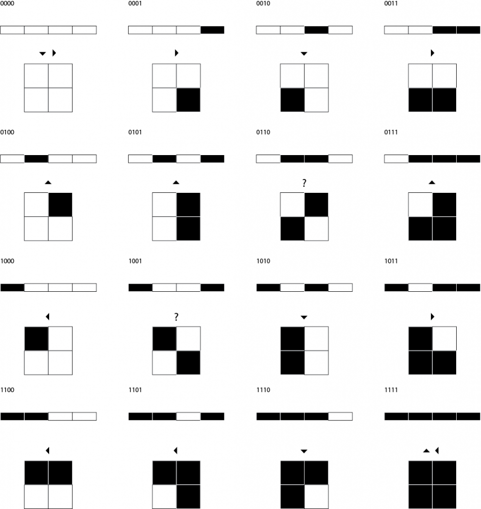
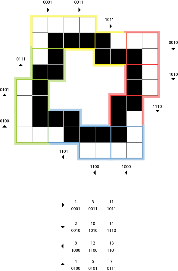
as we’re using a simple 2 * 2 kernel, there are very few possibilities ( only 16 actually ) to move the kernel when looking for the direction. here’s a table with the integers 0-15 in binary form, the 4 rectangles below the figure represent the bytes ( white=0, black = 1 ) & the squares are the kernel itself ; what we’ll use to actually determine the direction to move to (represented by the arrow above the box).
by sampling the right, bottom & bottom right pixels, this table allows us to quickly determine where we should go next but there are 2 flaws.
a minor flaw is that it contains both a 2 * 2 void square ( 0000 ) and a 2 * 2 full square ( 1111 ). this is not that bad ; as we select the first non-transparent pixel, it is usually located on the top left area of the picture so 0000 will head towards the bottom right & 1111 will head towards the top left.
the second flaw is more embarrassing though, it rises about the values 6 ( 0110 ) & 9 ( 1001 ) and form a diagonal pattern. in these cases, there is no way to tell where to send the kernel next, ending up in infinite loops. there are ways to deal with this problem but that’s beyond the scope of this article.
to prevent the infinite loops, I tried simply not to use those patterns.
which failed of course.
but it gave me an idea ; why not alter the binary shape so that this pattern doesn’t occur?
enter the Morphological operators.
the morphological operators work on binary images & perform very simple tests between a pixel & its neighborhood to determine whether or not to toggle a pixel.
this simple operators fill the smaller gaps that cause most of the infinite loops and applying this during the collection phase ( step 1 of the algorithm ) allows for not having to bother with ambiguous case anymore.
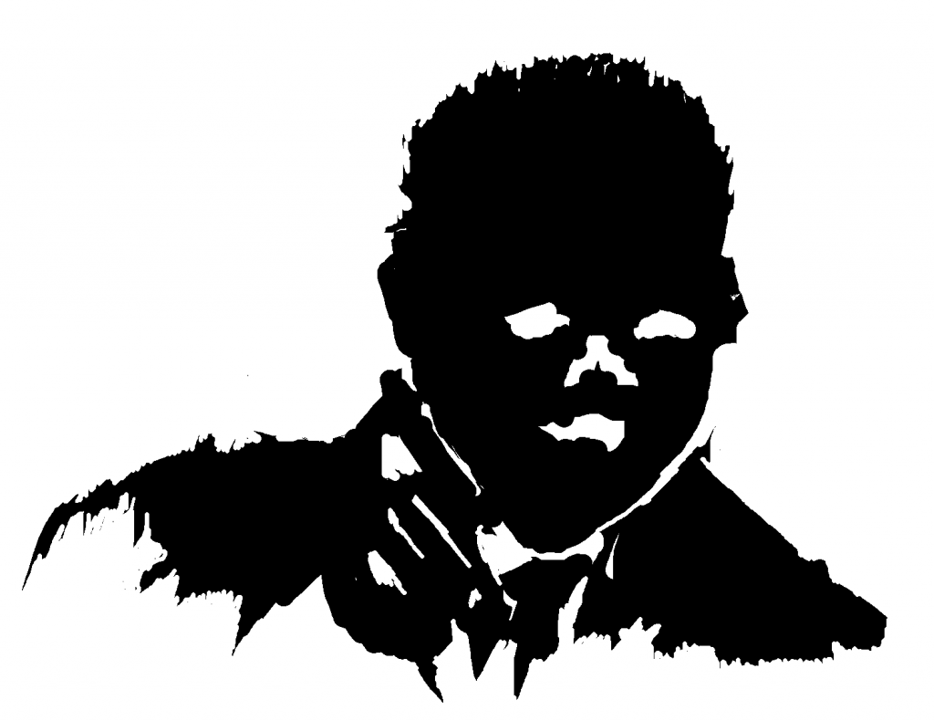
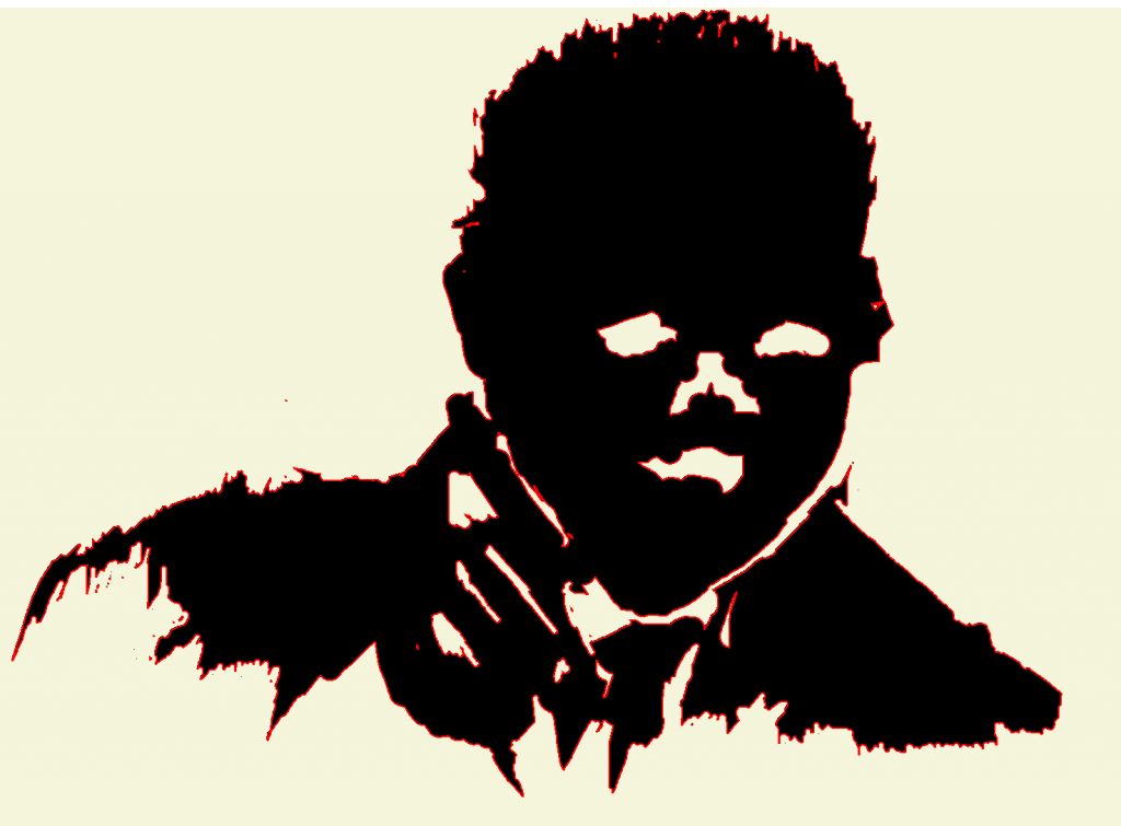
let’s take this burning head I did so it has a fair amount of ambiguous cases (click to view full size) especially in the bottom right corner.
trying a brute force marching square will fail, but applying the following kernel:
|
1 2 3 4 5 6 7 8 9 10 11 |
buffer[ id ] = 0; if (sum != 9 && sum > 1 ) { buffer[ id ] = 1; } //then if( sum > dilation )//dilation default: 5, lower = more greedy { buffer[ i ] = 1; } |
where sum is the sum of the neighboring pixels’ values, allows to preserve only the outline of the shape and gives the red outline (click to view full size)
if you look closely, you can follow the whole border without finding any ambiguous case + smaller elements (namely single pixels) are being discarded. now instead of 16 possibilities, we end up managing only 12 the Lookup table now looks like this:
the burning head vectorized output looks like this
the blue area is the vectorized outline and the orange line & dots is the simplified version of the path. nice isn’t it?
here’s the code of the marching squares method:
|
1 2 3 4 5 6 7 8 9 10 11 12 13 14 15 16 17 18 19 20 21 22 23 24 25 26 27 28 29 30 31 32 33 34 35 36 37 38 39 40 41 42 43 44 45 46 47 48 49 50 51 52 53 54 55 56 57 58 59 60 61 62 63 64 65 66 67 68 69 70 71 72 73 74 75 76 77 78 79 80 81 82 83 84 85 86 87 88 89 90 91 92 93 94 95 96 97 98 99 100 101 102 103 104 105 106 107 108 109 110 111 112 113 114 115 116 117 118 119 120 121 122 123 124 125 126 127 128 129 130 131 132 133 134 135 136 137 138 139 140 141 142 143 144 145 146 147 148 149 150 151 152 153 154 155 156 157 158 159 160 161 162 163 164 165 166 |
/** * function that performs a marching squares vectorization * @param imageOrCanvas an image or a canvas to vectorize, preferably a binary image. * @param color the color you want to vectorize ( between 0 & 0xFFFFFF ) * @param dilation value used in the dilation step ( 0 - 8 ) * @param maxIterations this prevents infinte loops ( default 10e5 ) * @returns {Array} a series of x, y coordinates * @constructor */ function MarchingSquares( imageOrCanvas, color, dilation, maxIterations ) { dilation = dilation == null ? 5 : dilation; maxIterations = maxIterations == null ? 10e5 : maxIterations; var canvas = document.createElement( "canvas" ); var w = canvas.width = imageOrCanvas.width + 4; var h = canvas.height = imageOrCanvas.height + 4; var context = canvas.getContext("2d"); context.fillStyle = "rgba(255,255,255,255)"; context.fillRect( 0,0, w, h ); context.drawImage( imageOrCanvas, 2, 2 ); var imgData= context.getImageData( 0,0,w,h ); var data = imgData.data; var buffer = new Int8Array(w*h); var path = []; var first = NaN; var i; var r = color >> 16 & 0xFF; var g = color >> 8 & 0xFF; var b = color & 0xFF; for( i = 0; i < data.length; i+=4 ) { // discard if the pixel has a different // color than what we're looking for if( data[ i ] != r && data[ i + 1 ] != g && data[ i + 2 ] != b ) { data[ i + 3 ] = 0; } else { data[ i + 3 ] = 1; } } //morphological operation extracting the border for( i = 0; i < data.length; i+=4 ) { id = i / 4; var sum = neighborSum( data, i, 4, 3 ); buffer[ id ] = 0; if (sum != 9 && sum > 1 ) { buffer[ id ] = 1; } } //morphological dilation //this prevents infinite loops for( i = 0; i < buffer.length; i++ ) { sum = neighborSum( buffer, i, 1, 0 ); if( sum > dilation ) { buffer[ i ] = 1; } // first non transparent pixel ( top left to current pixel ) if( isNaN( first ) && buffer[ i ] == 1 ) { first = i - w - 1; } } if( isNaN( first ) ) { console.log( "warning: no empty pixels was found, exiting." ); return []; } //morphological operators function neighborIds( id, stride ) { stride = stride || 1; var to = id - w * stride;//top var tr = to + stride;//top right var tl = to - stride;//top left var ri = id + stride; // right var le = id - stride;//left var bo = id + w * stride;//bottom var br = bo + stride;//bottom right var bl = bo - stride;//bottom left return [ tl, to, tr, le, id, ri, bl, bo, br ]; } function neighborValues( data, id, stride, offset ) { var values = []; var ids = neighborIds( id, stride ); ids.forEach( function( id ) { values.push( data[ id + offset ] ); }); return values; } function neighborSum( data, id, stride, offset ) { var values = neighborValues( data, id, stride, offset ); var sum = 0; values.forEach( function( value ) { sum += ( value > 0 ) ? 1 : 0; }); return sum; } //marching square var iteration = 0; var id = getDirection( buffer, first ); while( iteration++ < maxIterations ) { id = getDirection( buffer, id ); path.push( id % w - 1, parseInt( id / w ) - 1 ); if( id == first ) break;//done } //determine where to move next function getDirection( data, id ) { var ri = id + 1;// right pixel var bo = id + w;//bottom pixel var br = bo + 1;//bottom right pixel var x = 0; var y = 0; var key = data[ id ] << 3 | data[ ri ] << 2 | data[ bo ] << 1 | data[ br ]; if( key == 1 || key == 3 || key == 11 ) x = 1;// rightt if( key == 8 || key == 12 || key == 13 ) x = -1;// left if( key == 4 || key == 5 || key == 7 ) y = -1;// up if( key == 2 || key == 10 || key == 14 ) y = 1;// down return id + x + y * w; } return path; } |
it’s intentionally unoptimized for legibility but one would probably merge & inline the morphological operator, unfold & reorganize the way getDirection sets the x/y directions, reuse the canvas & the buffer instead of recreating it a.s.o.
and a standard call would go like :
|
1 2 3 4 5 6 7 8 9 10 11 12 13 14 15 16 17 18 19 20 21 22 23 24 25 26 27 28 29 30 31 32 33 |
function sample( img ) { var out = document.createElement( "canvas" ); out.width = img.width; out.height = img.height; document.body.appendChild( out ); var out_context = out.getContext("2d"); out_context.drawImage( img,0,0,out.width, out.height ); var path = MarchingSquares( img, 0, 5, 10e5 ); out_context.fillStyle = "rgba( 255,0,0,.35 )"; out_context.strokeStyle = "rgba( 255,0,0, .7 )"; out_context.lineWidth = 3; out_context.beginPath(); for( var i = 0; i < path.length; i+=2 ) { out_context.lineTo( path[ i ], path[ i+1 ] ); } out_context.closePath(); out_context.stroke(); out_context.fill(); } window.onload = function() { var img = document.getElementById( "my_favorite_unicorn" ); sample( segment( img,1 ) ); }; |
for instance calling this on a unicorn picture would give this kind of output

one of the greatest benefits of vectorization being to make images scale-free, my favourite results come from smaller images ; here are 2 32 * 32 pictures vectorized & simplified:
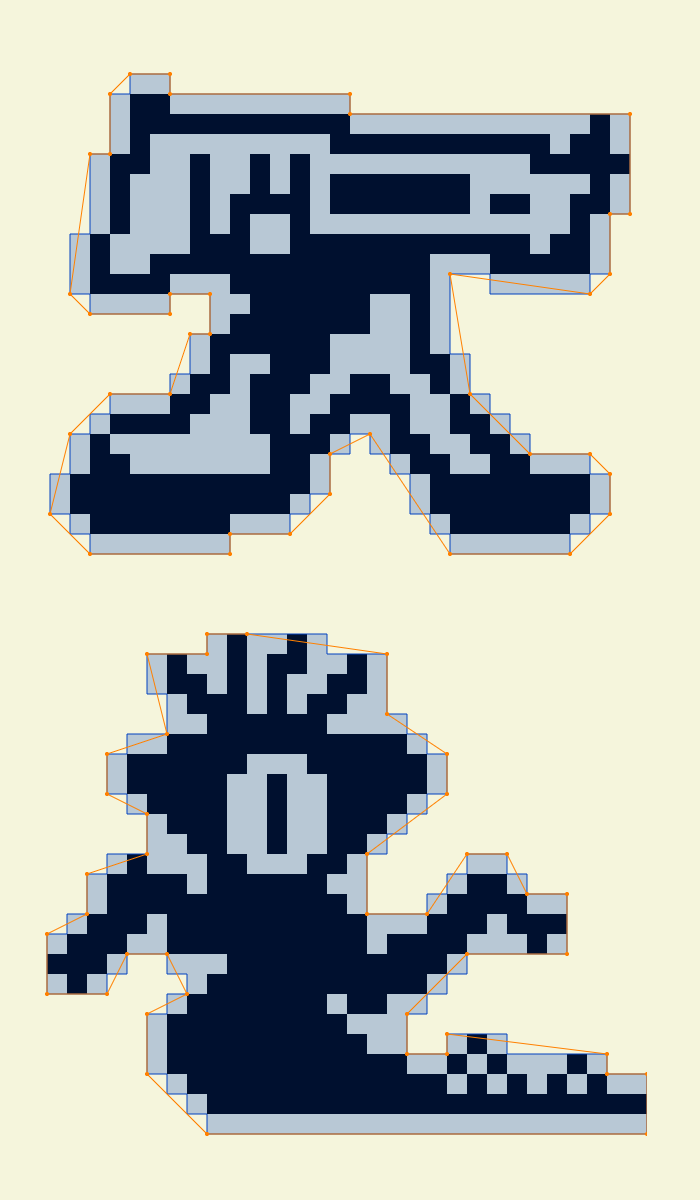
that’s far from bulletproof and I wouldn’t recommend using it in production but that’s a fun little algorithm to play with. it allows on the fly vectorization of free shapes to use in physics games for instance.
possible enhancements include, multiple shapes vectorization & triangulation, using better interpolation techniques than binary, using integral images (?!) also, I’d recommend reading this lovely article: Metaballs and marching squares by Jamie Wong.

Hello.
I want to use Marching square algorithm to detect the outline of a bitmap image in unity. Could you help me what should I do? Could I translate this code to c# for that?
Thanks